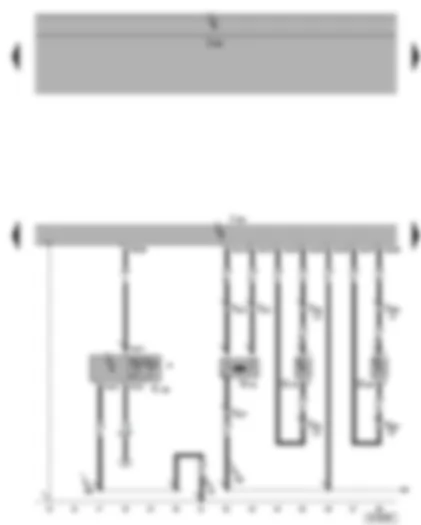
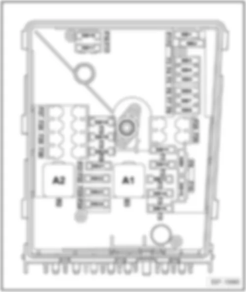
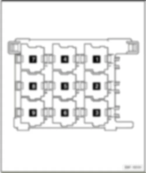
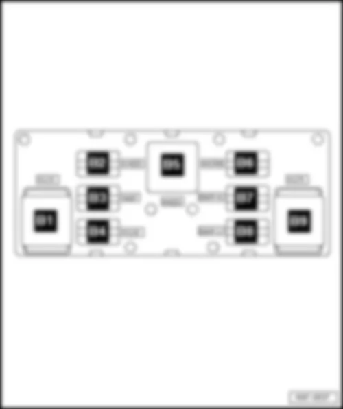
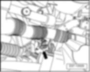
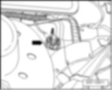
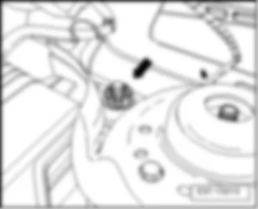
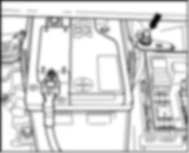
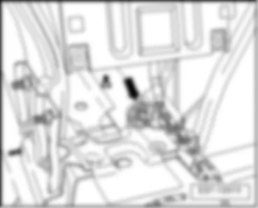
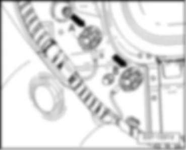
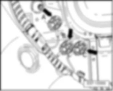
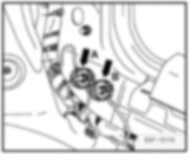
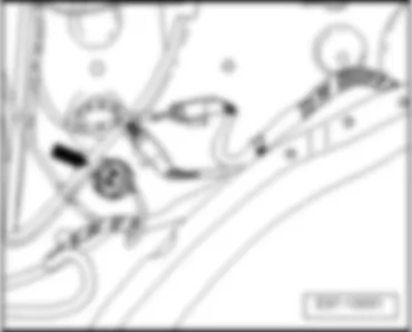
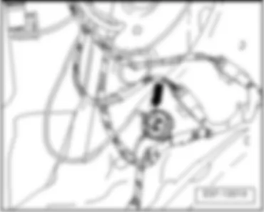
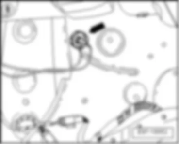
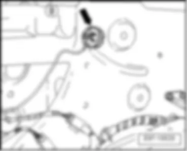
Wiring Diagram SEAT TOLEDO 2005 - Driver side airbag igniter - airbag coil connector - terminal 15 voltage supply relay 2 - steering column electronics control unit - airbag control unit

| A | Battery |
| C | Alternator |
| F138 | Airbag coil connector |
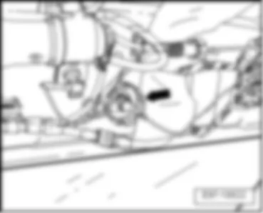
| J234 | Airbag control unit, behind the lower console |
| J519 | Onboard supply control unit |
| J527 | Steering column electronics control unit |
| J681 | Terminal 15 voltage supply relay 2, on onboard supply control unit (460) |
| N95 | Driver side airbag igniter |
| T4f | 4-pin connector |
| T12f | 12-pin connector |
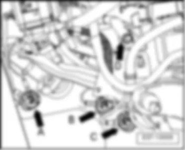
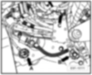
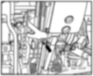
| T40 | 40-pin connector, under electronics box, in left engine compartment |
| T50 | 50-pin connector |
| 1 | Earth strap, battery - body |
| 507 | Screw connection (30), on fuse holder on battery |
| A38 | Positive connection 2 (15a), in dash panel wiring harness |
| A200 | Positive connection 5 (15a), in dash panel wiring harness |
| * | only models with alternator 90A/110A |
| ** | only models with alternator 140A |
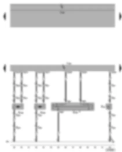
Wiring Diagram SEAT TOLEDO 2005 - Airbag control unit - side airbag crash sensors - front passenger side airbag igniter 1 - front passenger side airbag deactivated warning lamp
| G179 | Side airbag crash sensor on driver side |
| G180 | Side airbag crash sensor on front passenger side |
| J234 | Airbag control unit, behind the lower console |
| J519 | Onboard supply control unit |
| K145 | Front passenger side airbag deactivated warning lamp |
| N131 | Front passenger side airbag igniter 1 |
| T3j | 3-pin connector, near front passenger airbag |
| T4c | 4-pin connector |
| T20a | 20-pin connector, driver side A-pillar |
| T20b | 20-pin connector, front passenger side A-pillar |
| T50 | 50-pin connector |
| 43 | Earth point, lower part of right A-pillar |
| 109 | Earth connection, in airbag wiring harness |
| 368 | Earth connection 3, in main wiring harness |
| * | models with front passenger airbag deactivation only |
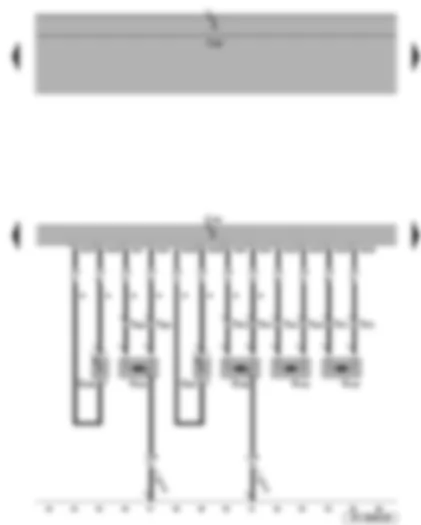
Wiring Diagram SEAT TOLEDO 2005 - Airbag control unit - side airbag igniter on driver side - key operated switch to deactivate front passenger side airbag - driver side belt switch
| E24 | Driver side belt switch |
| E224 | Key operated switch to deactivate front passenger side airbag |
| J234 | Airbag control unit, behind the lower console |
| J519 | Onboard supply control unit |
| N199 | Side airbag igniter on driver side |
| N200 | Side airbag igniter on front passenger side |
| T2i | 2-pin connector |
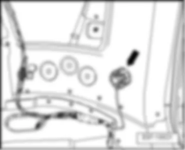
| T3k | 3-pin connector, under driver seat |
| T3l | 3-pin connector, under front passenger seat |
| T6g | 6-pin connector, in glove compartment |
| T50 | 50-pin connector |
| 109 | Earth connection, in airbag wiring harness |
| * | models with front passenger airbag deactivation only |
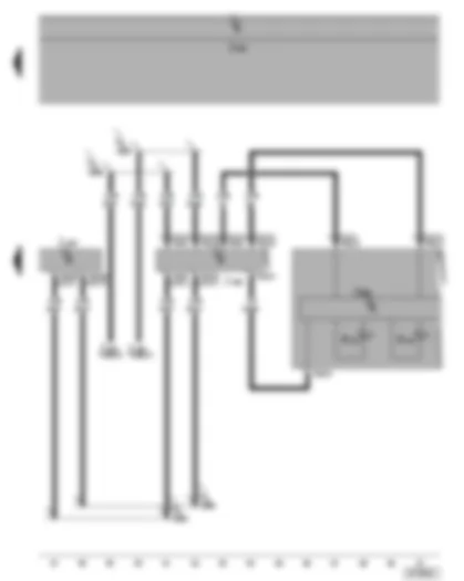
Wiring Diagram SEAT TOLEDO 2005 - Curtain airbag igniter - belt tensioner igniter - rear side airbag crash sensors - airbag control unit
| G256 | Rear side airbag crash sensor rear left |
| G257 | Rear side airbag crash sensor rear right |
| J234 | Airbag control unit, behind the lower console |
| J519 | Onboard supply control unit |
| N153 | Driver seat belt tensioner igniter |
| N154 | Front passenger seat belt tensioner igniter |
| N251 | Driver side curtain airbag igniter |
| N252 | Front passenger side curtain airbag igniter |
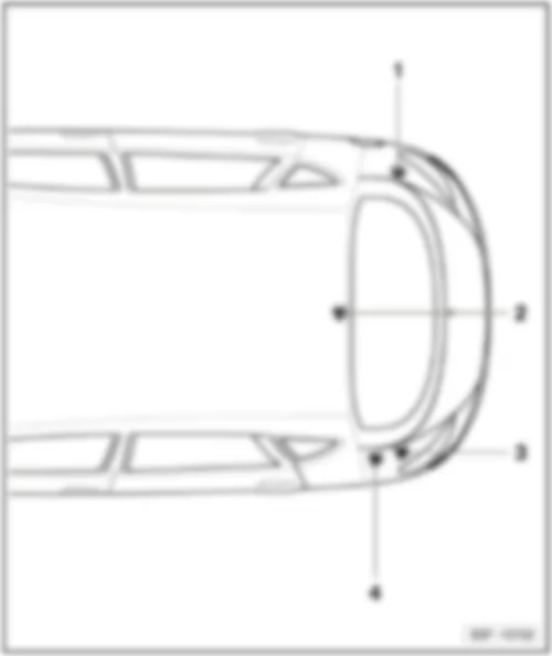
| T2e | 2-pin connector, behind B-pillar trim on lower left |
| T2f | 2-pin connector, behind B-pillar trim on lower right |
| T2g | 2-pin connector, near roof, rear left |
| T2h | 2-pin connector, near roof, rear right |
| T50 | 50-pin connector |
| 73 | Earth point, near centre, rear of roof |
| * | models with curtain airbag only |
Wiring Diagram SEAT TOLEDO 2005 - Airbag control unit - dash panel insert - data bus diagnostic interface - airbag warning lamp - seat belt warning system warning lamp
| J234 | Airbag control unit, behind the lower console |
| J285 | Display control unit in dash panel insert |
| J519 | Onboard supply control unit |
| J527 | Steering column electronics control unit |
| J533 | Data bus diagnostic interface, on left under dash panel |
| K19 | Seat belt warning system warning lamp |
| K75 | Airbag warning lamp |
| T20 | 20-pin connector |
| T20d | 20-pin connector |
| T36 | 36-pin connector |
| T50 | 50-pin connector |
| B383 | Connection 1 (drive train CAN bus, high), in main wiring harness |
| B390 | Connection 1 (drive train CAN bus, low), in main wiring harness |
| B397 | Connection 1 (convenience CAN bus, high), in main wiring harness |
| B406 | Connection 1 (drive train CAN bus, low), in main wiring harness |
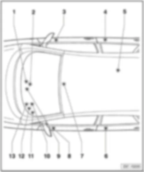
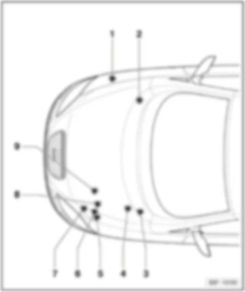
SEAT TOLEDO 2005 Control units overview
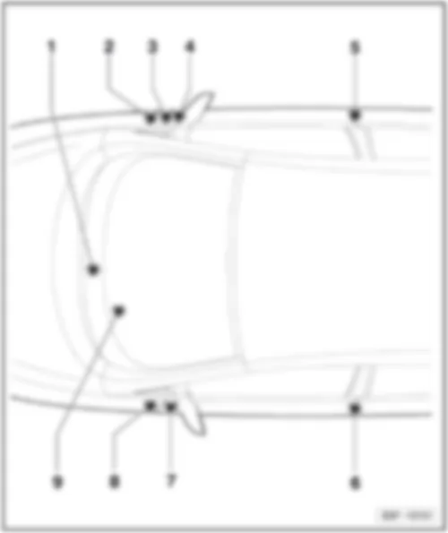
| 1 - | Convenience system central control unit -J393- |
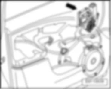
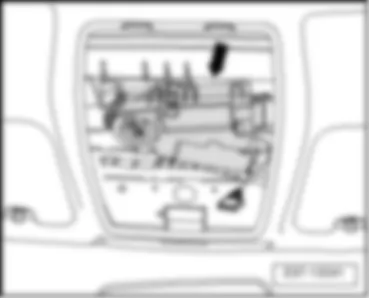
| q | Location → chapter |
| q | Connector assigment → chapter |
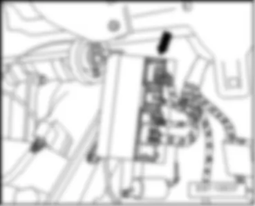
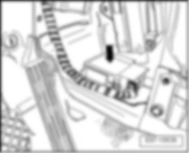
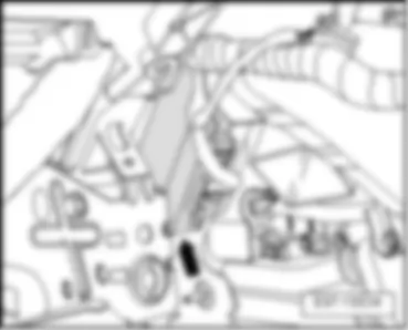
| 2 - | Airbag control unit -J234- |
| q | Location → chapter |
| q | Connector assigment → chapter |
| q | Connector assigment → chapter |
| 3 - | Front passenger door control unit -J387- |
| q | Location → chapter |
| q | Connector assigment → chapter |
| 4 - | Rear right door control unit -J389- |
| q | Location → chapter |
| q | Connector assigment → chapter |
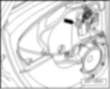
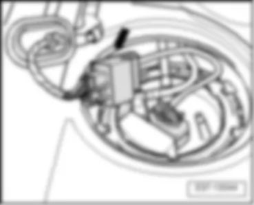
| 5 - | Fuel pump control unit -J538- |
| q | Location → chapter |
| q | Connector assigment → chapter |
| 6 - | Rear left door control unit -J388- |
| q | Location → chapter |
| q | Connector assigment → chapter |
| 7 - | Sliding sunroof adjustment control unit -J245- |
| q | Location → chapter |
| q | Connector assigment → chapter |
| 8 - | Driver door control unit -J386- |
| q | Location → chapter |
| q | Connector assigment → chapter |
| 9 - | Data bus diagnostic interface -J533- |
| q | Location → chapter |
| q | Connector assigment → chapter |
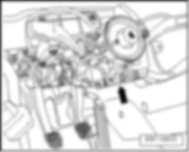
| 10 - | Steering column electronics control unit -J527- |
| q | Location → chapter |
| q | Connector assigment → chapter |
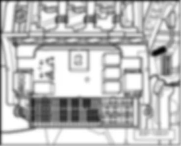
| 11 - | Onboard supply control unit -J519- |
| q | Location → chapter |
| q | Connector assigment → chapter |
| q | Description of signal, from November 2005 → chapter |
| q | Description of signal, from November 2007 → chapter |
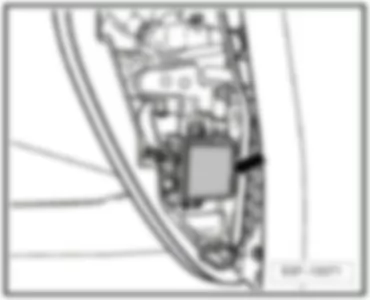
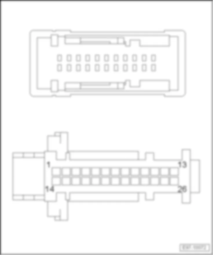
| 12 - | Headlight range control, control unit -J431- / Cornering light and headlight range control unit -J745- |
| q | Location → chapter |
| q | Connector assigment → chapter |
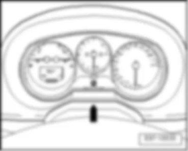
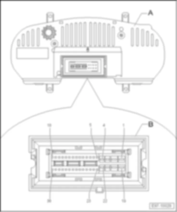
| 13 - | Control unit in dash panel insert -J285- |
| q | Location → chapter |
| q | Connector assigment → chapter |
|
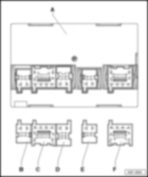
| Connector assigment: |
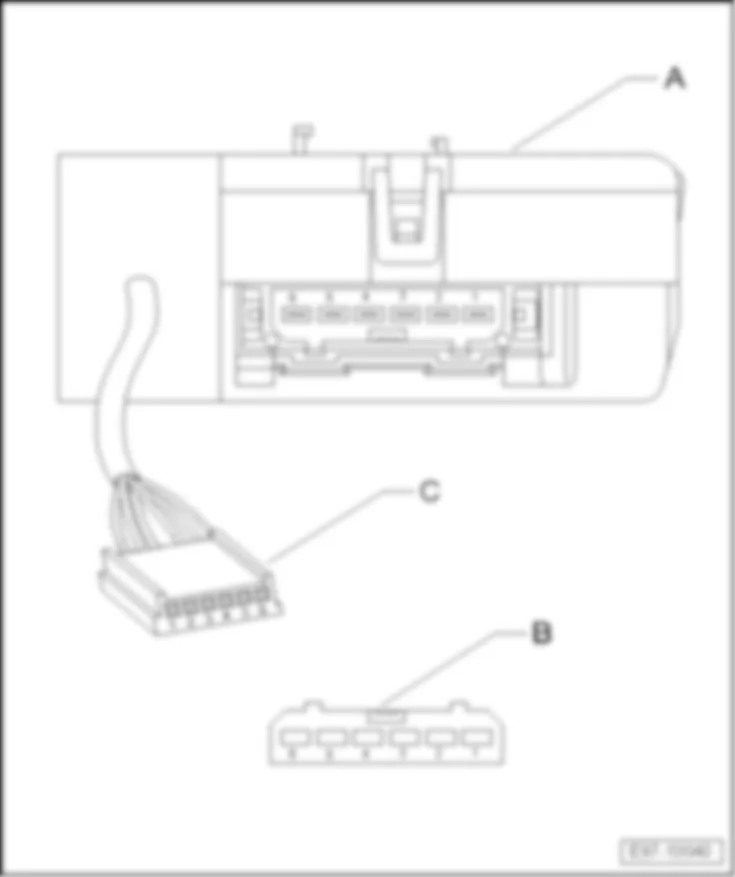
| A - | Convenience system central control unit -J393- |
| Pin connector: |
| B - | is not installed |
| C - | 18-pin connector -T18- |
| D - | 8-pin connector -T8- |
| E - | 6-pin connector -T6- |
| F - | 18-pin connector -T18a- |
| Back to overview → Anchor |
|
| Connector assigment: |
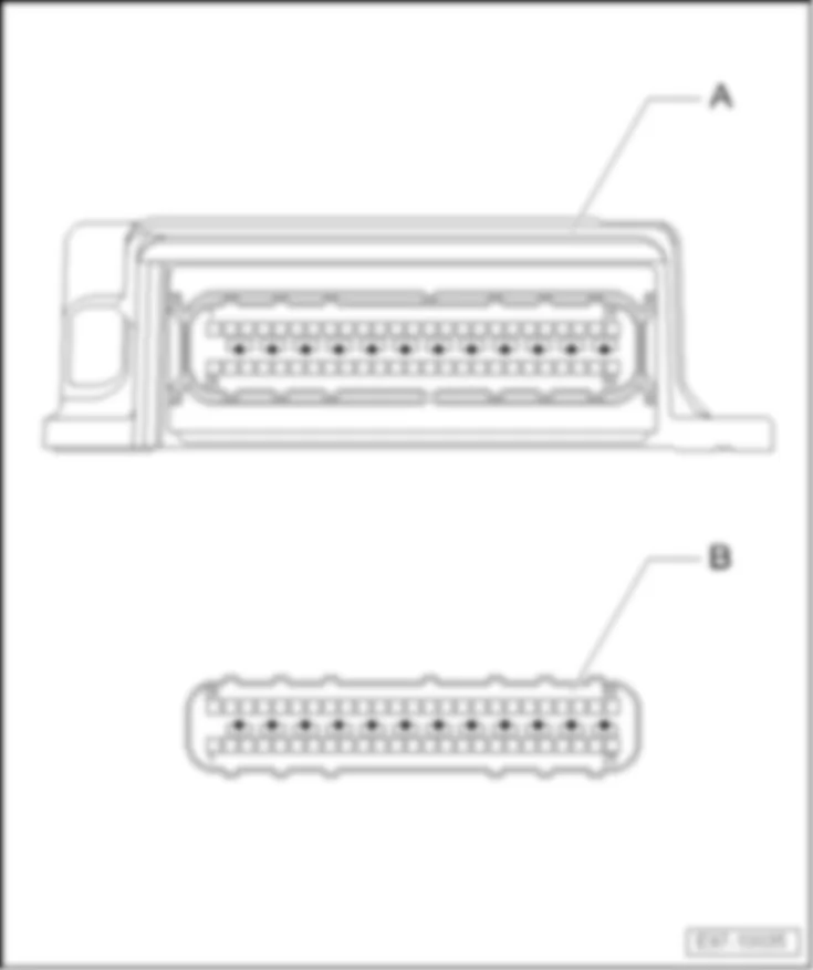
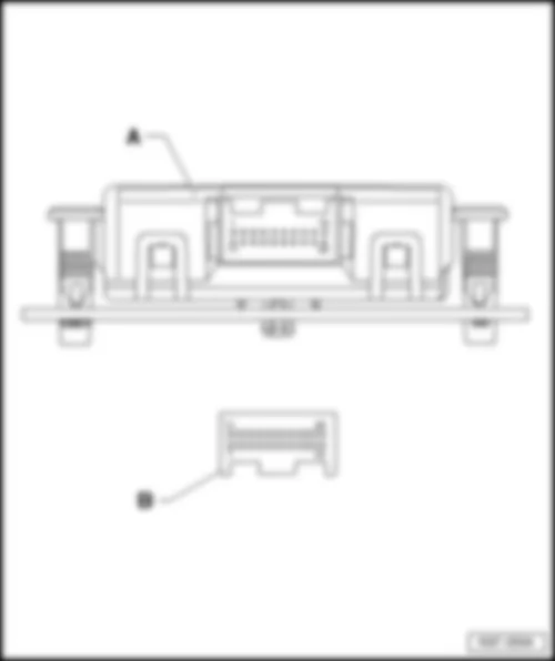
| A - | Airbag control unit -J234- |
| Pin connector: |
| B - | 50-pin connector -T50- |
| Back to overview → Anchor |
| Connector assigment: |
| A - | Airbag control unit -J234- |
| Pin connector: |
| B - | 75-pin connector -T75- |
| Back to overview → Anchor |
|
| Connector assigment: |
| A - | Front passenger door control unit -J387- |
| Pin connectors: |
| B - | 20-pin connector -T20h- |
| C - | 16-pin connector -T16a- |
| D - | 32-pin connector -T32a- |
| Back to overview → Anchor |
|
| Connector assigment: |
| A - | Rear right door control unit -J389- |
| Pin connector: |
| B - | 18-pin connector -T18c- |
| Back to overview → Anchor |
|
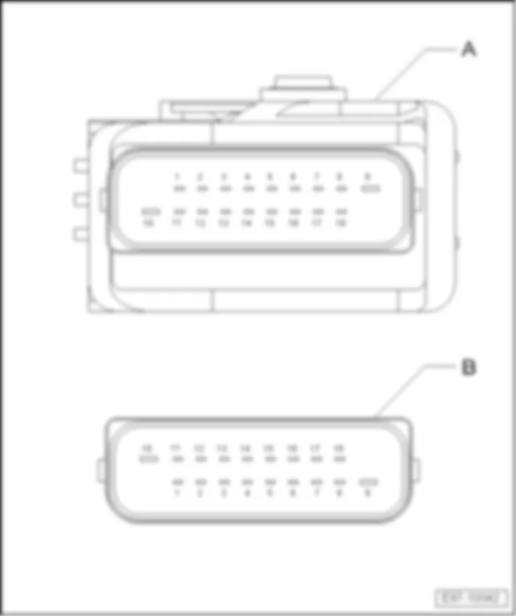
| Connector assigment: |
| A - | Fuel pump control unit -J538- |
| q | Engines BLR, BLY, BVY, BVZ, BWA, BZB and CAXC |
| Pin connector: |
| B - | 10-pin connector -T10l- |
| Back to overview → Anchor |
|
| Connector assigment: |
| A - | Rear left door control unit -J388- |
| Pin connector: |
| B - | 18-pin connector -T18b- |
| Back to overview → Anchor |
|
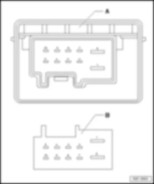
| Connector assigment: |
| A - | Sliding sunroof adjustment control unit -J245- |
| Pin connectors: |
| B - | 6-pin connector -T6c- |
| C - | 6-pin connector -T6d- |
| Back to overview → Anchor |
|
| Connector assigment: |
| A - | Driver door control unit -J386- |
| Pin connectors: |
| B - | 20-pin connector -T20g- |
| C - | 16-pin connector -T16b- |
| D - | 32-pin connector -T32- |
| Back to overview → Anchor |
|
| Connector assigment: |
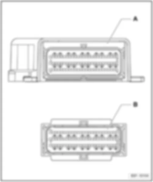
| A - | Data bus diagnostic interface -J533- |
| Pin connector: |
| B - | 20-pin connector -T20- |
| Back to overview → Anchor |
|
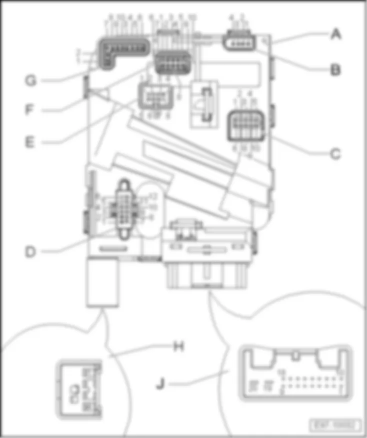
| Connector assigment: |
| A - | Steering column electronics control unit -J527- |
| Pin connectors: |
| B - | 4-pin connector, Tiptronic switch |
| C - | 10-pin connector, gear stick illumination and CCS |
| D - | 12-pin connector, ignition/starter switch and ignition key withdrawal lock |
| E - | 8-pin connector, windscreen wiper switch and multifunction switch |
| F - | 10-pin connector, steering angle sender (from May 2008, for left-handdrive vehicles only) |
| G - | 10-pin connector, airbag coil connector, operating unit and horn in steering wheel |
| H - | 4-pin connector -T4f- |
| J - | 20-pin connector -T20d- |
| Back to overview → Anchor |
|
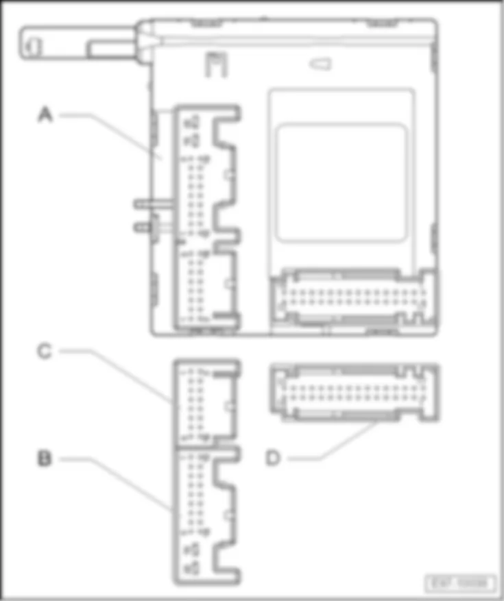
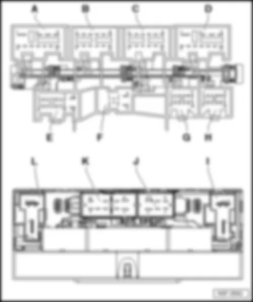
| Connector assigment: |
| Pin connectors: |
| A - | 11-pin connector |
| B - | 12-pin connector |
| C - | 12-pin connector |
| D - | 11-pin connector |
| E - | 16-pin connector |
| F - | 8-pin connector |
| G - | 12-pin connector |
| H - | Vacant |
| I - | 2-pin connector |
| J - | 6-pin connector |
| K - | 10-pin connector |
| L - | 2-pin connector |
| Back to overview → Anchor |
| Description of signal for onboard supply control unit -J519-, from November 2005 |
| Connector | Pin | Terminal | Equipment H | Equipment M |
| A | 1 | Supply (30), right lights | x | x |
| A | 2 | Right dipped beam signal output | x | x |
| A | 3 | Right main beam signal output | x | x |
| A | 4 | Right fog light signal output | x | - |
| A | 5 | Signal output for the activation of the gas discharge headlights on the right | x | - |
| A | 6 | Signal output for front right turn signal | x | x |
| A | 7 | Front left side light signal output | x | x |
| A | 8 | Signal output for left side repeater turn signal | x | x |
| A | 9 | Signal output for left side repeater turn signal | x | x |
| A | 10 | Fuel pump relay signal output | x | x |
| A | 11 | Voltage supply relay (50) signal output | x | x |
| B | 1 | Right reversing light signal output | x | x |
| B | 2 | - | - | |
| B | 3 | - | - | |
| B | 4 | Signal output for rear left fog light | x | x |
| B | 5 | Signal output for rear left fog light | x | x |
| B | 6 | - | - | |
| B | 7 | Footwell light signal output | x | x |
| B | 8 | - | - | |
| B | 9 | Right tail light signal output | x | x |
| B | 10 | Signal output for rear right turn signal | x | x |
| B | 11 | Interior lighting signal output, door contact switch | x | x |
| B | 12 | Illumination - switches and instruments (58d) signal output | x | x |
| C | 1 | Signal output for switching heated seat off | x | x |
| C | 2 | Left brake and tail light signal output | x | x |
| C | 3 | Signal output for rear right fog light | x | x |
| C | 4 | - | - | |
| C | 5 | Left seat backrest switch signal input | x | x |
| C | 6 | Right seat backrest switch signal input | x | x |
| C | 7 | - | - | |
| C | 8 | Number plate light signal output | x | x |
| C | 9 | High level brake light signal output | x | x |
| C | 10 | Left tail light signal output | x | x |
| C | 11 | Left tail light signal output | x | x |
| C | 12 | Left reversing light signal output | x | x |
| D | 1 | Supply (30), left lights | x | x |
| D | 2 | Left fog light signal output | x | - |
| D | 3 | Left main beam signal output | x | x |
| D | 4 | Left dipped beam signal output | x | x |
| D | 5 | Signal earth (31), right lights | x | x |
| D | 6 | Signal output for the activation of the gas discharge headlights on the left | x | - |
| D | 7 | Supply (15) output signal, engine relay | x | x |
| D | 8 | Headlight washer system relay signal output | x | x |
| D | 9 | Signal output for right side repeater turn signal | x | x |
| D | 10 | Front right side light signal output | x | x |
| D | 11 | Signal output for front left turn signal | x | x |
| E | 1 | Side light switch signal input | x | x |
| E | 2 | Brake light switch signal input | x | x |
| E | 3 | Come-Home potentiometer earth | x | x |
| E | 4 | Come-Home potentiometer supply | x | x |
| E | 5 | - | - | |
| E | 6 | Fog light switch signal input | x | - |
| E | 7 | Selector lever lock P/N signal input | x | x |
| E | 8 | Dipped beam switch input signal | x | x |
| E | 9 | - | - | |
| E | 10 | - | - | |
| E | 11 | - | - | |
| E | 12 | Come-Home potentiometer input signal | x | x |
| E | 13 | Rear fog light switch signal input | x | x |
| E | 14 | Automatic driving lights switch signal input | x | x |
| E | 15 | - | - | |
| E | 16 | Light switch position "0" signal input | x | x |
| F | 1 | Signal input (50), diagnosis | x | x |
| F | 2 | Signal input (15), diagnosis engine | x | x |
| F | 3 | LIN-Bus | x | x |
| F | 4 | Signal (L) alternator | x | x |
| F | 5 | Bonnet switch input signal | x | x |
| F | 6 | Reversing light switch signal input | x | x |
| F | 7 | Input signal for reference voltage (30) | x | x |
| F | 8 | Input signal for earth - reference voltage (31) | x | x |
| G | 1 | Voltage supply signal input (50) for ignition/starter switch | x | x |
| G | 2 | Hazard warning light system warning lamp signal output | x | x |
| G | 3 | Heated rear window warning lamp signal output | x | x |
| G | 4 | Signal earth for illumination regulators - switches and instruments (31) | x | x |
| G | 5 | - | - | |
| G | 6 | Heated rear window button input signal | x | x |
| G | 7 | Convenience CAN-L | x | x |
| G | 8 | Convenience CAN-H | x | x |
| G | 9 | Hazard warning light switch signal input | x | x |
| G | 10 | Supply for switches and instruments illumination regulator | x | x |
| G | 11 | Voltage supply signal input (15) for ignition/starter switch | x | x |
| G | 12 | Switches and instruments illumination regulator signal input | x | x |
| H | 1 | - | - | |
| H | 2 | - | - | |
| H | 3 | - | - | |
| H | 4 | - | - | |
| H | 5 | - | - | |
| H | 6 | - | - | |
| H | 7 | - | - | |
| H | 8 | - | - | |
| H | 9 | - | - | |
| H | 10 | - | - | |
| H | 11 | - | - | |
| H | 12 | - | - | |
| I | 1 | Supply (75a) input | x | x |
| I | 2 | Supply (75x) output | x | x |
| J | 1 | Washer pump supply input | x | x |
| J | 2 | Washer pump motor and rear window wiper motor signal output | x | x |
| J | 3 | Horn supply input | x | x |
| J | 4 | Washer pump motor and rear window wiper motor signal output | x | x |
| J | 5 | Washer pump earth (31) | x | x |
| J | 6 | Horn signal output | x | x |
| K | 1 | Heated rear window signal output | x | x |
| K | 2 | - | - | |
| K | 3 | - | - | |
| K | 4 | - | - | |
| K | 5 | Supply input (30G) | x | x |
| K | 6 | Heated rear window supply input | x | x |
| K | 7 | - | - | |
| K | 8 | - | - | |
| K | 9 | - | - | |
| K | 10 | Supply output (30G) | x | x |
| L | 1 | Interior supply input (15) | x | x |
| L | 2 | Interior supply output (15) | x | x |
| Description of signal for onboard supply control unit -J519-, from November 2007 |
| Connector | Pin | Terminal | Equipment H | Equipment M |
| A | 1 | Supply (30), right lights | x | x |
| A | 2 | Right dipped beam signal output | x | x |
| A | 3 | Right main beam signal output | x | x |
| A | 4 | Right fog light signal output | x | - |
| A | 5 | Signal output for the activation of the gas discharge headlights on the right | x | - |
| A | 6 | Signal output for front right turn signal | x | x |
| A | 7 | Front left side light signal output | x | x |
| A | 8 | Signal output for left side repeater turn signal | x | x |
| A | 9 | Signal earth (31), left lights | x | x |
| A | 10 | Fuel pump relay signal output | x | x |
| A | 11 | Voltage supply relay (50) signal output | x | x |
| B | 1 | Right reversing light signal output | x | x |
| B | 2 | - | - | |
| B | 3 | - | - | |
| B | 4 | Signal output for rear left fog light | x | x |
| B | 5 | Right brake and tail light signal output (Altea XL and Freetrack) | x | x |
| B | 6 | - | - | |
| B | 7 | Footwell light signal output | x | x |
| B | 8 | - | - | |
| B | 9 | Right brake and tail light signal output (Altea and Toledo), right tail light signal output (Altea XL and Freetrack) | x | x |
| B | 10 | Signal output for rear right turn signal | x | x |
| B | 11 | Interior lighting signal output, door contact switch | x | x |
| B | 12 | Illumination - switches and instruments (58d) signal output | x | x |
| C | 1 | Signal output for switching heated seat off | x | x |
| C | 2 | Left brake and tail light signal output (Altea XL and Freetrack) | x | x |
| C | 3 | Signal output for rear right fog light | x | x |
| C | 4 | - | - | |
| C | 5 | Left seat backrest switch signal input | x | x |
| C | 6 | Right seat backrest switch signal input | x | x |
| C | 7 | - | - | |
| C | 8 | Number plate light signal output | x | x |
| C | 9 | High level brake light signal output | x | x |
| C | 10 | Left brake and tail light signal output (Altea and Toledo), left tail light signal output (Altea XL and Freetrack) | x | x |
| C | 11 | Left tail light signal output | x | x |
| C | 12 | Left reversing light signal output | x | x |
| D | 1 | Supply (30), left lights | x | x |
| D | 2 | Left fog light signal output | x | - |
| D | 3 | Left main beam signal output | x | x |
| D | 4 | Left dipped beam signal output | x | x |
| D | 5 | Signal earth (31), right lights | x | x |
| D | 6 | Signal output for the activation of the gas discharge headlights on the left | x | - |
| D | 7 | Supply (15) output signal, engine relay | x | x |
| D | 8 | Headlight washer system relay signal output | x | x |
| D | 9 | Signal output for right side repeater turn signal | x | x |
| D | 10 | Front right side light signal output | x | x |
| D | 11 | Signal output for front left turn signal | x | x |
| E | 1 | Side light switch signal input | x | x |
| E | 2 | Brake light switch signal input | x | x |
| E | 3 | Come-Home potentiometer earth | x | x |
| E | 4 | Come-Home potentiometer supply | x | x |
| E | 5 | - | - | |
| E | 6 | Fog light switch signal input | x | - |
| E | 7 | Selector lever lock P/N signal input | x | x |
| E | 8 | Dipped beam switch input signal | x | x |
| E | 9 | - | - | |
| E | 10 | - | - | |
| E | 11 | - | - | |
| E | 12 | Come-Home potentiometer input signal | x | x |
| E | 13 | Rear fog light switch signal input | x | x |
| E | 14 | Automatic driving lights switch signal input | x | x |
| E | 15 | - | - | |
| E | 16 | Light switch position "0" signal input | x | x |
| F | 1 | Signal input (50), diagnosis | x | x |
| F | 2 | Signal input (15), diagnosis engine | x | x |
| F | 3 | LIN-Bus | x | x |
| F | 4 | Signal (L) alternator | x | x |
| F | 5 | Bonnet switch input signal | x | x |
| F | 6 | Reversing light switch signal input | x | x |
| F | 7 | Input signal for reference voltage (30) | x | x |
| F | 8 | Input signal for earth - reference voltage (31) | x | x |
| G | 1 | Voltage supply signal input (50) for ignition/starter switch | x | x |
| G | 2 | Hazard warning light system warning lamp signal output | x | x |
| G | 3 | Heated rear window warning lamp signal output | x | x |
| G | 4 | Signal earth for illumination regulators - switches and instruments (31) | x | x |
| G | 5 | - | - | |
| G | 6 | Heated rear window button input signal | x | x |
| G | 7 | Convenience CAN-L | x | x |
| G | 8 | Convenience CAN-H | x | x |
| G | 9 | Hazard warning light switch signal input | x | x |
| G | 10 | Supply for switches and instruments illumination regulator | x | x |
| G | 11 | Voltage supply signal input (15) for ignition/starter switch | x | x |
| G | 12 | Switches and instruments illumination regulator signal input | x | x |
| H | 1 | - | - | |
| H | 2 | - | - | |
| H | 3 | - | - | |
| H | 4 | - | - | |
| H | 5 | - | - | |
| H | 6 | - | - | |
| H | 7 | - | - | |
| H | 8 | - | - | |
| H | 9 | - | - | |
| H | 10 | - | - | |
| H | 11 | - | - | |
| H | 12 | - | - | |
| I | 1 | Supply (75a) input | x | x |
| I | 2 | Supply (75x) output | x | x |
| J | 1 | Washer pump supply input | x | x |
| J | 2 | Washer pump motor and rear window wiper motor signal output | x | x |
| J | 3 | Horn supply input | x | x |
| J | 4 | Washer pump motor and rear window wiper motor signal output | x | x |
| J | 5 | Washer pump earth (31) | x | x |
| J | 6 | Horn signal output | x | x |
| K | 1 | Heated rear window signal output | x | x |
| K | 2 | - | - | |
| K | 3 | - | - | |
| K | 4 | - | - | |
| K | 5 | Supply input (30G) | x | x |
| K | 6 | Heated rear window supply input | x | x |
| K | 7 | - | - | |
| K | 8 | - | - | |
| K | 9 | - | - | |
| K | 10 | Supply output (30G) | x | x |
| L | 1 | Interior supply input (15) | x | x |
| L | 2 | Interior supply output (15) | x | x |
|
| Connector assigment: |
| A - | Headlight range control, control unit -J431- |
| Pin connector: |
| B - | 26-pin connector -T26- |
| Back to overview → Anchor |
|
| Connector assigment: |
| A - | Control unit in dash panel insert -J285- |
| Pin connector: |
| B - | 36-pin connector -T36- |
| Back to overview → Anchor |

 English
