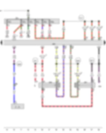
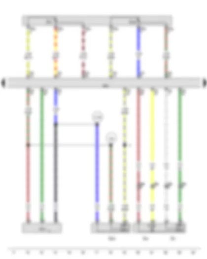
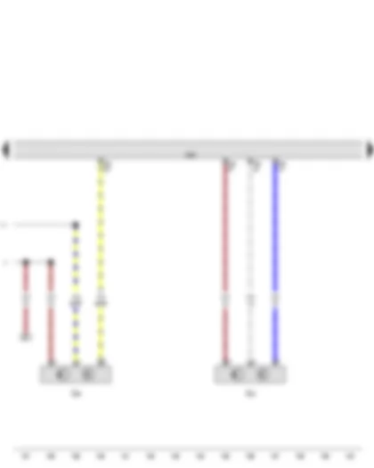
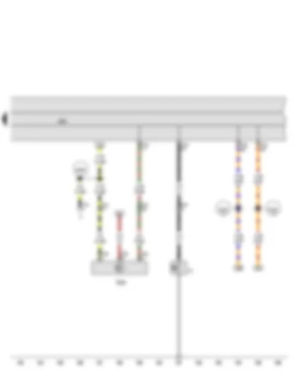
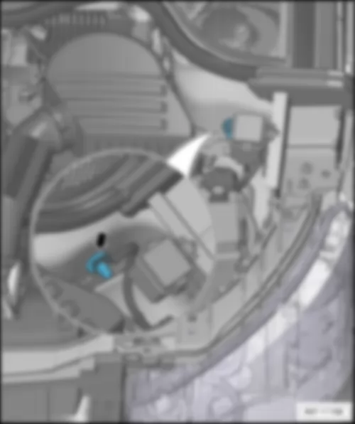
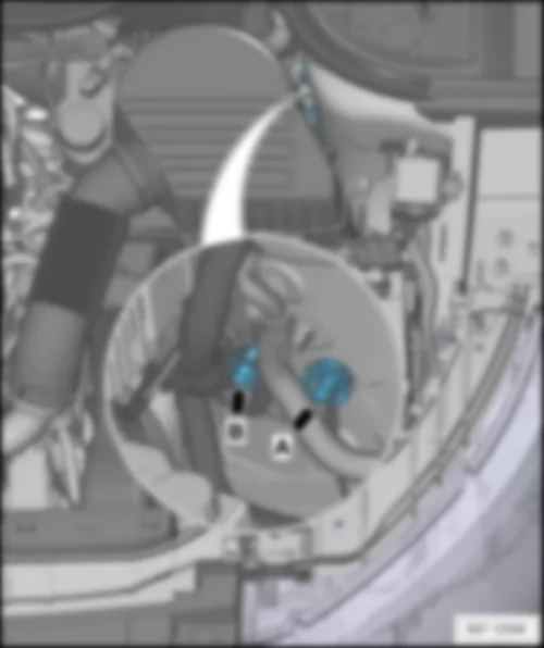
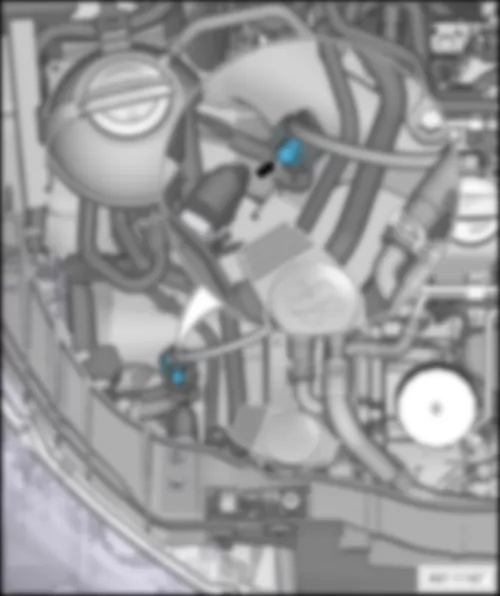
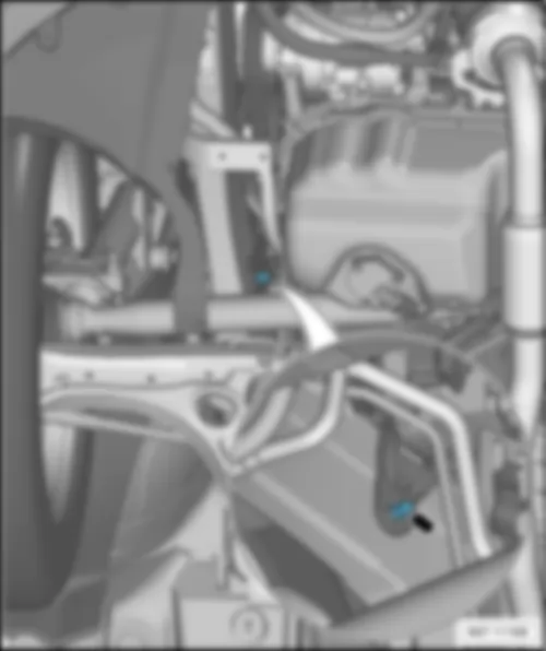
Wiring Diagram AUDI A1 2014 - Terminal 30 voltage supply relay - Engine control unit

J317 | Terminal 30 voltage supply relay |
J623 | Engine control unit |
ST2 | Fuse carrier 2 |
SC2 | Fuse 2 on fuse holder C |
SC7 | Fuse 7 on fuse holder C |
SF9 | Fuse 9 in fuse holder F |
SF10 | Fuse 10 in fuse holder F |
T94 | 94-pin connector |
B146 | Positive connection 1 (87), in interior wiring harness |
B272 | Positive connection (30), in main wiring harness |
B299 | Positive connection 3 (30), in main wiring harness |
B350 | Positive connection 1 (87a) in main wiring harness |
* | see applicable current flow diagram for fuse assignment |
*2 | From May 2012 |
*3 | Up to April 2012 |
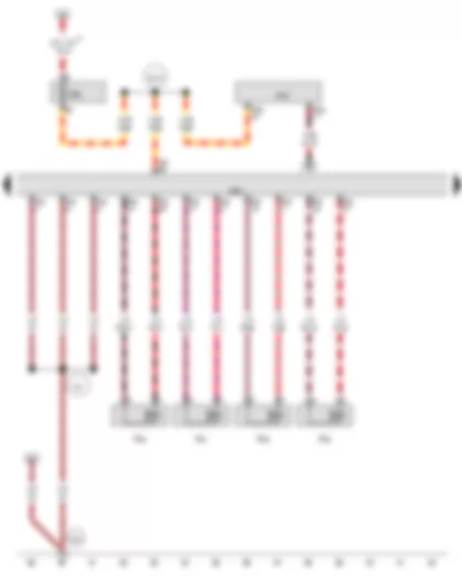
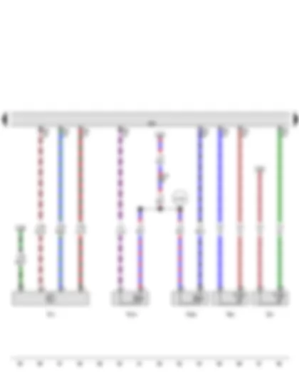
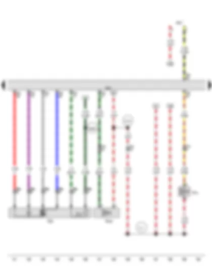
Wiring Diagram AUDI A1 2014 - Engine control unit - Starter relay 1 - Starter relay 2
B | Starter |
C | Alternator |
C1 | Voltage regulator |
J329 | Terminal 15 voltage supply relay |
J623 | Engine control unit |
J906 | Starter relay 1 |
J907 | Starter relay 2 |
SC1 | Fuse 1 on fuse holder C |
SC2 | Fuse 2 on fuse holder C |
ST3 | Fuse carrier 3 |
SC3 | Fuse 3 on fuse holder C |
SC4 | Fuse 4 on fuse holder C |
SC5 | Fuse 5 on fuse holder C |
SC6 | Fuse 6 on fuse holder C |
T8kl | 8-pin connector, black |
T94 | 94-pin connector |
B146 | Positive connection 1 (87), in interior wiring harness |
B273 | Positive connection (15), in main wiring harness |
B465 | Connection 1, in main wiring harness |
B528 | Connection 1 (LIN bus) in main wiring harness |
D97 | Connection (50), in engine compartment right wiring harness |
D101 | Connection 1 in engine compartment wiring harness |
* | see applicable current flow diagram for fuse assignment |
*2 | From May 2012 |
*3 | Up to April 2012 |
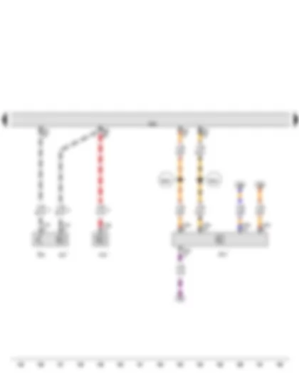
Wiring Diagram AUDI A1 2014 - Engine control unit - Injector - cylinder 1 - Injector - cylinder 2 - Injector - cylinder 3 - Injector - cylinder 4
J519 | Onboard supply control unit |
J623 | Engine control unit |
N30 | Injector, cylinder 1 |
N31 | Injector, cylinder 2 |
N32 | Injector, cylinder 3 |
N33 | Injector, cylinder 4 |
SF6 | Fuse 6 in fuse holder F |
T52c | 52-pin connector |
T60 | 60-pin connector |
T94 | 94-pin connector |
85 | Earth connection 1, in engine compartment wiring harness |
673 | Earth point 3, on front of left longitudinal member |
D210 | Connection (50), in engine compartment wiring harness |
* | see applicable current flow diagram for basic equipment |
*2 | From May 2012 |
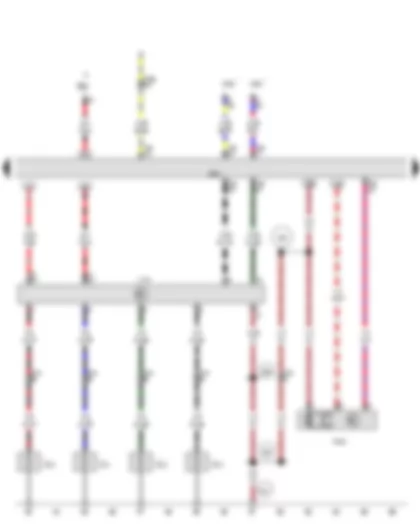
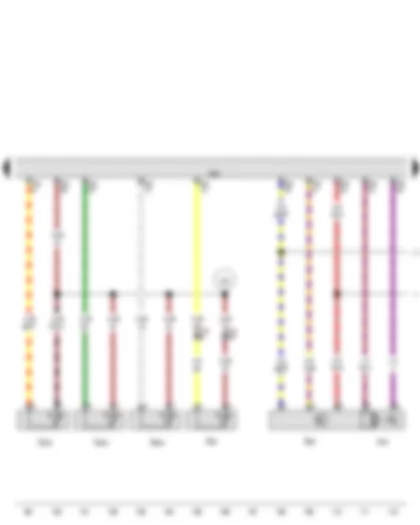
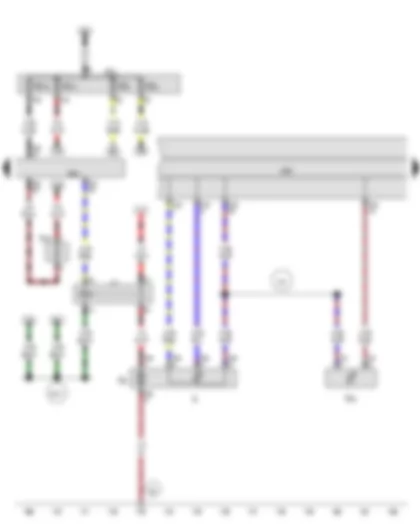
Wiring Diagram AUDI A1 2014 - Automatic glow period control unit - Low heat output relay - Engine control unit - Glow plug 1 - Glow plug 2 - Glow plug 3 - Glow plug 4 - Pump for exhaust gas recirculation cooler
J179 | Automatic glow period control unit |
J359 | Low heat output relay |
J360 | High heat output relay |
J623 | Engine control unit |
Q10 | Glow plug 1 |
Q11 | Glow plug 2 |
Q12 | Glow plug 3 |
Q13 | Glow plug 4 |
SB6 | Fuse 6 on fuse holder B |
T10c | 10-pin connector |
T14 | 14-pin connector, black |
T60 | 60-pin connector |
T94 | 94-pin connector |
V400 | Pump for exhaust gas recirculation cooler |
283 | Earth point 2, engine prewiring harness |
366 | Earth connection 1, in main wiring harness |
367 | Earth connection 2, in main wiring harness |
671 | Earth point 1, on front of left longitudinal member |
* | see applicable current flow diagram |
*2 | see applicable current flow diagram for fuse assignment |
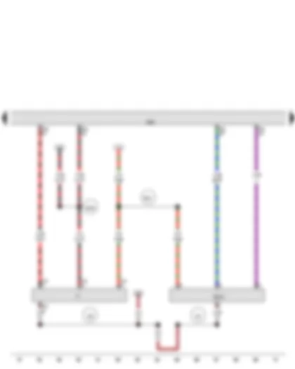
Wiring Diagram AUDI A1 2014 - Brake light switch - Clutch position sender - Engine control unit
F | Brake light switch |
G476 | Clutch position sender |
J623 | Engine control unit |
T4k | 4-pin connector |
T94 | 94-pin connector |
391 | Earth connection 26, in main wiring harness |
392 | Earth connection 27, in main wiring harness |
B335 | Connection 1 (54), in main wiring harness |
B351 | Positive connection 2 (87a) in main wiring harness |
* | Only models with manual gearbox |
Wiring Diagram AUDI A1 2014 - Charge pressure sender - Intake air temperature sender - Accelerator position sender - Pressure differential sender - Engine control unit
G31 | Charge pressure sender |
G42 | Intake air temperature sender |
G79 | Accelerator position sender |
G185 | Accelerator position sender 2 |
G505 | Pressure differential sender |
G701 | Gearbox neutral position sender |
J623 | Engine control unit |
T6ag | 6-pin connector |
T8kl | 8-pin connector, black |
T94 | 94-pin connector |
220 | Earth connection (sender earth), in engine wiring harness |
D195 | Connection 1 (5V) in engine compartment wiring harness |
* | Only models with start/stop system |
*2 | Only models with manual gearbox |
*3 | Gradually discontinued |
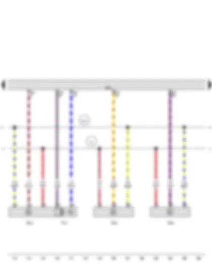
Wiring Diagram AUDI A1 2014 - Coolant temperature sender - Air mass meter - Fuel temperature sender - Engine control unit - Fuel pressure regulating valve - Fuel metering valve
G62 | Coolant temperature sender |
G70 | Air mass meter |
G81 | Fuel temperature sender |
J623 | Engine control unit |
N276 | Fuel pressure regulating valve |
N290 | Fuel metering valve |
T14 | 14-pin connector |
T60 | 60-pin connector |
T94 | 94-pin connector |
D180 | Connection (87a), in engine compartment wiring harness |
* | Wiring colour depends on equipment |
Wiring Diagram AUDI A1 2014 - Throttle valve potentiometer - Radiator outlet coolant temperature sender - Exhaust gas temperature sender 1 - Exhaust gas temperature sender 3 - Exhaust gas temperature sender 4 - Throttle valve module - Engine control unit
G69 | Throttle valve potentiometer |
G83 | Radiator outlet coolant temperature sender |
G235 | Exhaust gas temperature sender 1 |
G495 | Exhaust gas temperature sender 3 |
G648 | Exhaust gas temperature sender 4 |
J338 | Throttle valve module |
J623 | Engine control unit |
T14 | 14-pin connector, black |
T60 | 60-pin connector |
T94 | 94-pin connector |
131 | Earth connection 2, in engine compartment wiring harness |
328 | Earth connection 2 (sender earth), in engine compartment wiring harness |
D141 | Connection (5V) in engine prewiring harness |
Wiring Diagram AUDI A1 2014 - Exhaust gas recirculation potentiometer - Fuel pressure sender - Position sender for charge pressure positioner - Engine control unit - Exhaust gas recirculation valve
G212 | Exhaust gas recirculation potentiometer |
G247 | Fuel pressure sender |
G581 | Position sender for charge pressure positioner |
J623 | Engine control unit |
N18 | Exhaust gas recirculation valve |
T60 | 60-pin connector |
131 | Earth connection 2, in engine compartment wiring harness |
D141 | Connection (5V) in engine prewiring harness |
* | see applicable current flow diagram for manually controlled heater |
Wiring Diagram AUDI A1 2014 - Engine speed sender - Hall sender - Engine control unit
G28 | Engine speed sender |
G40 | Hall sender |
J623 | Engine control unit |
T60 | 60-pin connector |
131 | Earth connection 2, in engine compartment wiring harness |
D141 | Connection (5V) in engine prewiring harness |
Wiring Diagram AUDI A1 2014 - Lambda probe - Engine control unit - Charge pressure control solenoid valve - Exhaust gas recirculation cooler changeover valve
G39 | Lambda probe |
J293 | Radiator fan control unit |
J623 | Engine control unit |
N75 | Charge pressure control solenoid valve |
N345 | Exhaust gas recirculation cooler changeover valve |
T6a | 6-pin connector, black |
T14 | 14-pin connector, black |
T60 | 60-pin connector |
T94 | 94-pin connector |
Z19 | Lambda probe heater |
B326 | Positive connection 12 (30a) in main wiring harness |
C11 | Connection in radiator fan wiring harness |
D181 | Connection 2 (87a) in engine compartment wiring harness |
* | see applicable current flow diagram for radiator fan |
Wiring Diagram AUDI A1 2014 - Cruise control system switch - Engine control unit
E45 | Cruise control system switch |
J527 | Steering column electronics control unit |
J533 | Data bus diagnostic interface |
J623 | Engine control unit |
J764 | Control unit for electronic steering column lock |
T16a | 16-pin connector |
T16f | 16-pin connector |
T20d | 20-pin connector |
T94 | 94-pin connector |
B383 | Connection 1 (powertrain CAN bus, high), in main wiring harness |
B390 | Connection 1 (powertrain CAN bus, low), in main wiring harness |
* | see applicable current flow diagram |
*2 | According to equipment |
*3 | Only models with cruise control system (CCS) |
Wiring Diagram AUDI A1 2014 - Fuel gauge sender - Fuel system pressurisation pump - Coolant shortage indicator sender - Fuel pump relay - Control unit in dash panel insert - Engine control unit - Heater element for crankcase breather
G | Fuel gauge sender |
G6 | Fuel system pressurisation pump |
G32 | Coolant shortage indicator sender |
J17 | Fuel pump relay |
J285 | Control unit in dash panel insert |
J623 | Engine control unit |
N79 | Heater element for crankcase breather |
SD2 | Fuse 2 on fuse holder D |
ST2 | Fuse carrier 2 |
SD5 | Fuse 5 on fuse holder D |
SD10 | Fuse 10 on fuse holder D |
SD16 | Fuse 16 on fuse holder D |
T2t | 2-pin connector |
T5e | 5-pin connector |
T32f | 32-pin connector |
T94 | 94-pin connector |
62 | Earth point, right C-pillar |
401 | Earth connection (sender earth), in interior wiring harness |
B147 | Positive connection 2 (87), in interior wiring harness |
* | Optional equipment |
Wiring Diagram AUDI A1 2014 - Oil pressure switch - Oil level and oil temperature sender - Control unit in dash panel insert
F1 | Oil pressure switch |
G266 | Oil level and oil temperature sender |
J285 | Control unit in dash panel insert |
T3e | 3-pin connector |
T14 | 14-pin connector, black |
T16 | 16-pin connector |
T32f | 32-pin connector |
B486 | Connection 22, in main wiring harness |
B708 | Connection 1 (dash panel insert CAN bus high) in main wiring harness |
B709 | Connection 1 (dash panel insert CAN bus low) in main wiring harness |
* | see applicable current flow diagram for basic equipment |
*2 | Diagnostic connection |
*3 | According to equipment |
AUDI A1 2014 Overview of relays
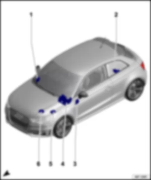
Overview of relays Note
Overview also valid for 5-door models! |
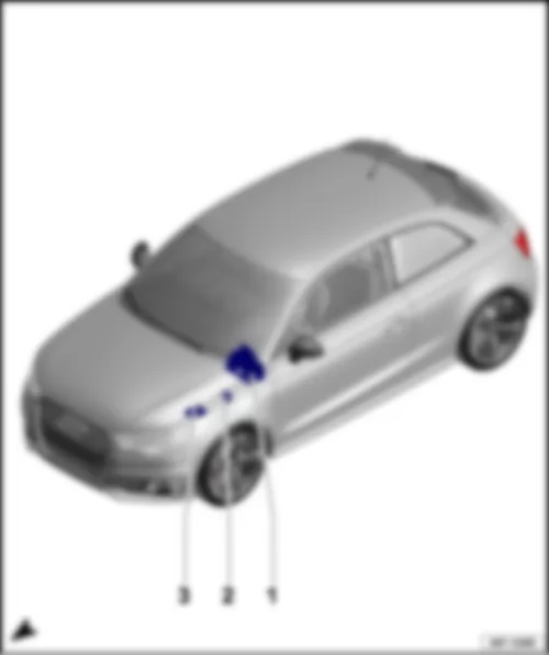
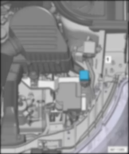
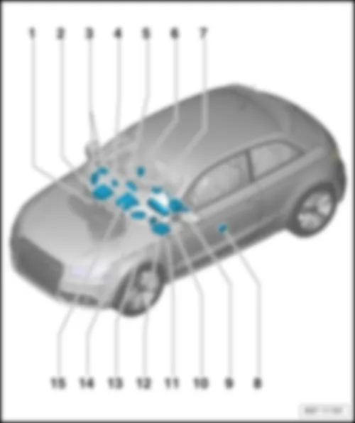
1 - | Relay/fuse holder F -SF- |
q | Components: -J9-; -J17-; -J39-; -J59-; -J271-; -J317-; -J329-; -J359-; -J360-; -J413-; -J570-; -J682-; -J807-; -J906-; -J907-; -J910-; -J925- |
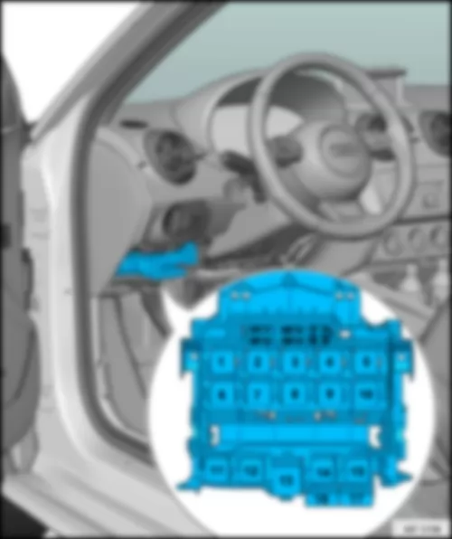
q | Fitting location for models with left-hand drive, up to October 2014: → chapter |
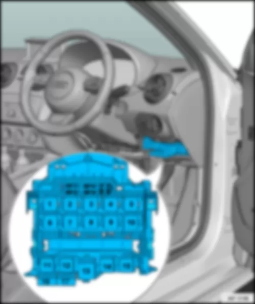
q | Fitting location for models with right-hand drive, up to October 2014: → chapter |
q | Fitting location for models with left-hand drive, from November 2014: → chapter |
q | Fitting location for models with right-hand drive, from November 2014: → chapter |
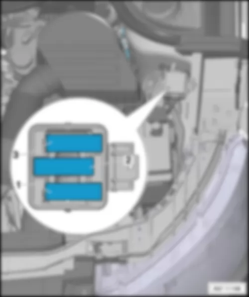
2 - | Engine compartment box, up to October 2014 |
q | Components: -J368-; -J369-; -J496- |
q | Fitting location: → Chapter |
q | Not for S1 version models, from January 2014 |
3 - | Electronics box: relay / fuse holder B -SB-, Fuse holder H -SH-, from January 2014 |
q | Components:-J271-; -J317-; -J360-; -J368-; -J369-; -JJ906-; -J907- |
q | Fitting location for S1 models, from January 2014: → chapter |
q | Fitting location for models from November 2014: → chapter |
AUDI A1 2014 Relay/ fuse holder F SF
Note
|
1 - | Headlight washer system relay -J39- |
q | Position 1.1 |
1 - | Horn relay -J413- |
q | Position 1.2 |
2 - | Terminal 15 voltage supply relay -J329- |
3 - | X-contact relief relay -J59- |
4 - | Fuel pump relay -J17- → Note |
q | Position 4.1 |
4 - | Heater element relay -J925- |
q | Position 4.2 |
5 - | High heat output relay -J360- |
6 - | Terminal 50 voltage supply relay -J682- → Note |
6 - | Starter relay 1 -J906- |
q | Position 6.1 |
6 - | Starter relay 2 -J907- |
q | Position 6.2 |
7 - | Heated rear window relay -J9- |
8 - | Motronic current supply relay -J271- → Note → Note |
8 - | Terminal 30 voltage supply relay -J317- → Note → Note |
8 - | Relay for power sockets -J807- → Note |
9 - | Low heat output relay -J359- |
10 - | Motronic current supply relay -J271- → Note → Note |
10 - | Terminal 30 voltage supply relay -J317- → Note → Note |
10 - | Relay for power sockets -J807- → Note |
11 - | Vacant |
12 - | Vacant |
13 - | Voltage stabiliser 2 -J570- |
14 - | Vacant |
15 - | Relay for automatic anti-dazzle interior mirror -J910- |
16 - | Vacant |
17 - | Vacant |
Note
|
1 - | Headlight washer system relay -J39- |
q | Position 1.1 |
1 - | Horn relay -J413- |
q | Position 1.2 |
2 - | Terminal 15 voltage supply relay -J329- |
3 - | X-contact relief relay -J59- |
4 - | Fuel pump relay -J17- → Note |
q | Position 4.1 |
4 - | Heater element relay -J925- |
q | Position 4.2 |
5 - | High heat output relay -J360- |
6 - | Terminal 50 voltage supply relay -J682- → Note |
6 - | Starter relay 1 -J906- |
q | Position 6.1 |
6 - | Starter relay 2 -J907- |
q | Position 6.2 |
7 - | Heated rear window relay -J9- |
8 - | Motronic current supply relay -J271- → Note → Note |
8 - | Terminal 30 voltage supply relay -J317- → Note → Note |
8 - | Relay for power sockets -J807- → Note |
9 - | Low heat output relay -J359- |
10 - | Motronic current supply relay -J271- → Note → Note |
10 - | Terminal 30 voltage supply relay -J317- → Note → Note |
10 - | Relay for power sockets -J807- → Note |
11 - | Relay for automatic anti-dazzle interior mirror -J910- |
12 - | Vacant |
13 - | Voltage stabiliser 2 -J570- |
14 - | Vacant |
15 - | Vacant |
16 - | Vacant |
17 - | Vacant |
AUDI A1 2014 Relay/ fuse holder F SF
Note
|
1 - | Headlight washer system relay -J39- |
q | Position 1.1 |
1 - | Horn relay -J413- |
q | Position 1.2 |
2 - | Terminal 15 voltage supply relay -J329- |
3 - | X-contact relief relay -J59- |
4 - | Fuel pump relay -J17- → Note |
5 - | Vacant |
6 - | Relay for automatic anti-dazzle interior mirror -J910- |
q | Position 6.1 |
6 - | Engine component current supply relay -J757- |
q | Position 6.2 |
7 - | Heated rear window relay -J9- |
8 - | Relay for power sockets -J807- |
9 - | Low heat output relay -J359- |
10 - | Vacant |
11 - | Vacant |
12 - | Vacant |
13 - | Vacant |
14 - | Vacant |
15 - | Vacant |
16 - | Vacant |
17 - | Vacant |
AUDI A1 2014 Engine compartment box, up to October 2014
|
1 - | Auxiliary coolant pump relay -J496- |
2 - | Wiper motor switch-over relay 1 -J368- |
3 - | Wiper motor switch-over relay 2 -J369- |
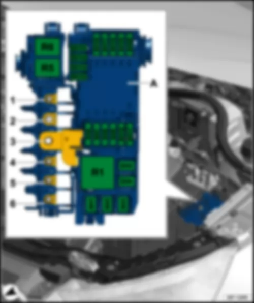
A - | Electronics box |
R1 - | High heat output relay -J360- |
R5 - | Wiper motor switch-over relay 1 -J368- |
R6 - | Wiper motor switch-over relay 2 -J369- |
Note
AUDI A1 2014 Electronics box: relay / fuse holder B SB , Fuse holder H SH for models from November 2014 only
|
A - | Electronics box |
R1 - | High heat output relay -J360- |
R5 - | Wiper motor switch-over relay 1 -J368- |
R6 - | Wiper motor switch-over relay 2 -J369- |
Note
|
AUDI A1 2014 Overview of control units
Overview of control units Note
Overview also valid for 5-door models! |
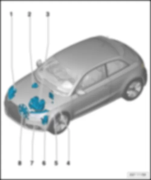
1 - | Output module for right headlight -J668- |
q | Fitting location: in right headlight |
1 - | Control unit for right daytime running light and side light -J861- |
q | Fitting location: in right gas discharge headlight |
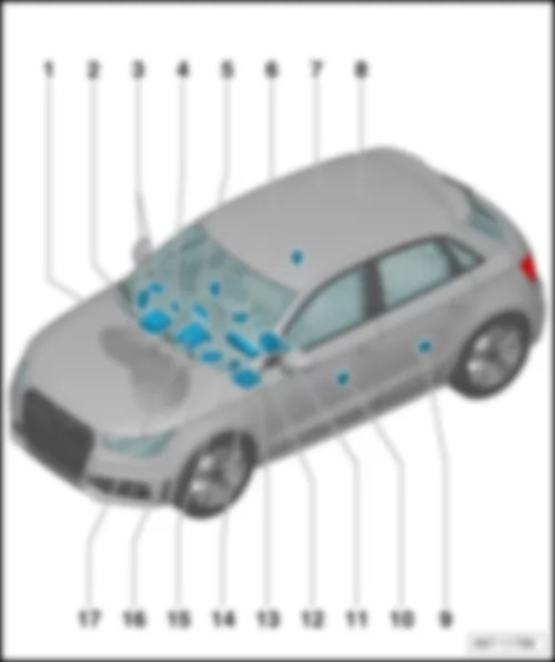
2 - | ABS control unit -J104- |
q | Fitting location and connectors: → chapter |
3 - | Automatic gearbox control unit -J217- |
q | Fitting location: on gearbox |
3 - | Mechatronic unit for dual clutch gearbox -J743- |
q | Fitting location: on gearbox |
4 - | Engine control unit -J623- |
q | Location and connectors, 154-pin → chapter |
q | Location and connectors, 196-pin → chapter |
5 - | Automatic glow period control unit -J179- |
q | Fitting location: → Chapter |
6 - | Power steering control unit -J500- |
q | Fitting location and connectors → chapter |
7 - | Output module for left headlight -J667- |
q | Fitting location: in left headlight |
7 - | Control unit for left daytime running light and side light -J860- |
q | Fitting location: in left gas discharge headlight |
8 - | Radiator fan control unit -J293- |
q | Fitting location: on radiator |
AUDI A1 2014 ABS control unit J104
|
A - | ABS control unit -J104- |
B - | 38-pin connector -T38a- |
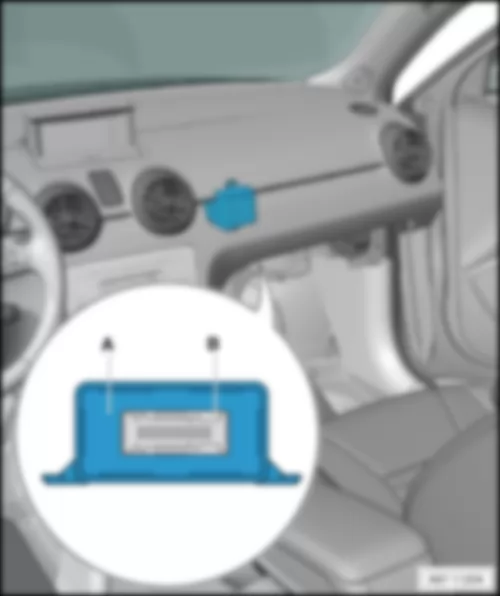
AUDI A1 2014 Engine control unit J623
|
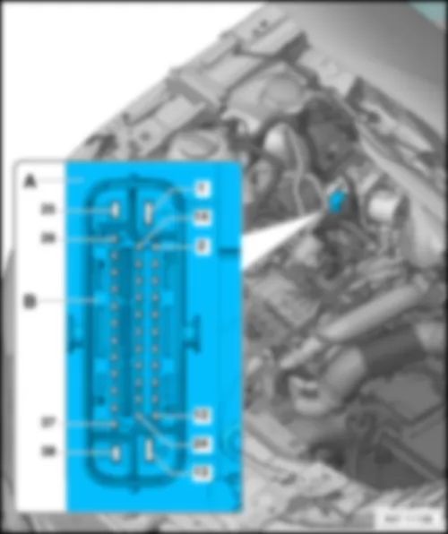
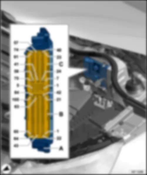
A - | Engine control unit -J623- |
B - | 60-pin connector, black -T60- |
C - | 94-pin connector, black -T94- |
|
A - | Engine control unit -J623- |
B - | 105-pin connector, black -T105- |
C - | 91-pin connector, black -T91- |
Note
|
1 - | Automatic glow period control unit -J179- |
AUDI A1 2014 Power steering control unit J500
|
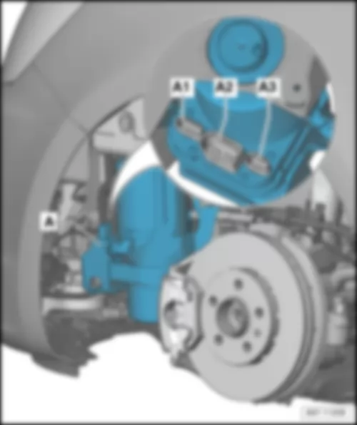
A - | Power steering control unit -J500- |
A1 - | 4-pin connector -T4a- (plug B) |
A2 - | 2-pin connector -T2b- (plug A) |
A3 - | 3-pin connector -T3b- (plug C) |
AUDI A1 2014 Overview of fuses
Overview of fuses Note
Overview also valid for 5-door models! |
1 - | Fuse holder D -SD- |
q | Fitting location for models with left-hand drive: → chapter |
q | Fitting location for models with right-hand drive: → anchor |
2 - | Fuse holder A -SA- |
q | Fitting location: → Chapter |
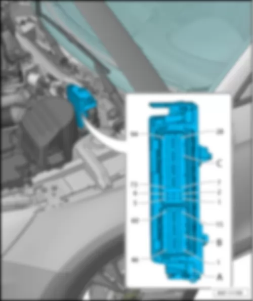
3 - | fuse holder C -SC- |
q | Fitting location for models with left-hand drive: → chapter |
q | Fitting location for models with right-hand drive: → anchor |
4 - | Relay/fuse holder F -SF- |
q | Fitting location for models with left-hand drive: → chapter |
q | Fitting location for models with right-hand drive: → anchor |
5 - | Fuse holder B -SB-, Fuse holder H -SH- |
q | Location in electronics box: → chapter |
q | For S1 version models only, from January 2014 |
q | For models from November 2014 only. |
6 - | Fuse holder B -SB- |
q | Fitting location for models with battery in engine compartment, up to October 2014: → chapter |
q | Fitting location for models with battery in engine compartment, up to October 2014: → Anchor |
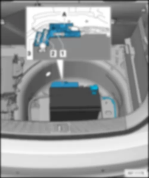
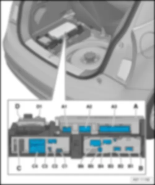
AUDI A1 2014 Fuse holder A SA
|
A - | Battery isolation igniter -N253- |
1 - | Fuse 1 on fuse holder A -SA1-, → Chapter |
2 - | Fuse 2 on fuse holder A -SA2-, → Chapter |
3 - | Fuse 3 on fuse holder A -SA3-, → Chapter |
Fuses in fuse holder A -SA- |
No. | Current Flow Diagram designation | Nominal value | Function/component | Terminal | ||
1 | - | Fuse 1 on fuse holder A -SA1- | - | Vacant | 30 | |
2 | - | Fuse 2 on fuse holder A -SA2- | 110 A | - | Onboard supply Engine component supply | 30 |
3 | - | Fuse 3 on fuse holder A -SA3- | - | Vacant | 30 |
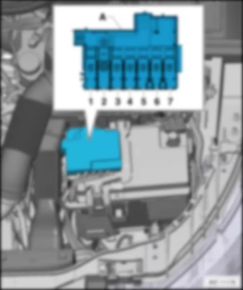
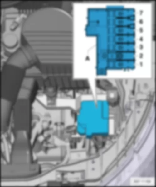
AUDI A1 2014 Fuse holder B SB
Note
|
A - | Fuse holder B -SB- |
1 - | Fuse 1 on fuse holder B -SB1-, → Chapter |
2 - | Fuse 2 on fuse holder B -SB2-, → Chapter |
3 - | Fuse 3 on fuse holder B -SB3-, → Chapter |
4 - | Fuse 4 on fuse holder B -SB4-, → Chapter |
5 - | Fuse 5 on fuse holder B -SB5-, → Chapter |
6 - | Fuse 6 on fuse holder B -SB6-, → Chapter |
7 - | Fuse 7 on fuse holder B -SB7-, → Chapter |
Fuses in fuse holder B -SB- |
No. | Current Flow Diagram designation | Nominal value | Function/component | Terminal | ||
1 | - | Fuse 1 on fuse holder B -SB1- | 175 A | - | Alternator -C- | 30 |
2 | - | Fuse 2 on fuse holder B -SB2- | 40 A | - | Low heat output relay -J359- Heater element for auxiliary air heater -Z35- | 30 |
3 | - | Fuse 3 on fuse holder B -SB3- | 110 A → Note1) | - | Onboard supply → Note1) Engine component supply → Note1) | 30 |
4 | - | Fuse 4 on fuse holder B -SB4- | 80 A | - | Power steering control unit -J500- | 30 |
5 | - | Fuse 5 on fuse holder B -SB5- | 50 A → Note2) 40 A → Note3) | - | Radiator fan thermal switch -F18- Radiator fan control unit -J293- | 30 |
6 | - | Fuse 6 on fuse holder B -SB6- | 50 A | - | Automatic glow period control unit -J179- | 30 |
7 | - | Fuse 7 on fuse holder B -SB7- | 60 A | - | High heat output relay -J360- Battery monitor control unit -J367- → Note1) Auxiliary heater element -Z35- | 30 |
AUDI A1 2014 Fuses in electronics box in fuse holder B SB / Fuse holder H SH
|
A - | Electronics box with fuse holder B -SB- and Fuse holder H -SH- |
1 - | Fuse 1 on fuse holder B -SB1- |
2 - | Fuse 2 on fuse holder B -SB2- |
3 - | Terminal 30 battery + |
4 - | Fuse 3 on fuse holder B -SB3- |
5 - | Fuse 4 on fuse holder B -SB4- |
6 - | Fuse 5 on fuse holder B -SB5- |
|
No. | Current Flow Diagram designation | Nominal value | Function/component | Terminal | ||
1 | - | Fuse 1 on fuse holder B -SB1- | 110 A → Note4) 50 A → Note5) | - | Onboard supply → Note4) Engine component supply → Note4) Radiator fan control unit -J293- → Note5) Radiator fan -V7- → Note5) | 30 |
2 | - | Fuse 2 on fuse holder B -SB2- | 250 A | - | Alternator -C- Voltage regulator -C1- | 30 |
3 | - | Terminal 30 | - | - | Battery + | 30 |
4 | - | Fuse 3 on fuse holder B -SB3- | 80 A | - | Power steering control unit -J500- | 30 |
5 | - | Fuse 4 on fuse holder B -SB4- | 50 A → Note6) | - | Automatic glow period control unit -J179- → Note6) Glow plug 1 -Q10- Glow plug 2 -Q11- Glow plug 3 -Q12- Glow plug 4 -Q13- | 30 |
6 | - | Fuse 5 on fuse holder B -SB5- | 50 A → Note7) - → Note8) - → Note9) | - | Radiator fan control unit -J293- → Note7) Radiator fan -V7- → Note7) - | 30 |
- | Fuse 1 (30) -S204- → Note9) | 125 A | - | Onboard supply → Note8) Engine component supply → Note8) | 30 |
Note
|
No. | Current Flow Diagram designation | Nominal value | Function/component | Terminal | ||
1 | - | Fuse 1 on fuse holder H -SH1- | 40 A | - | Heater element for auxiliary air heater -Z35-, stage 1 | 30 |
2 | - | Fuse 2 on fuse holder H -SH2- | 30 A | - | Radiator fan control unit -J293- Radiator fan -V7- | 30 |
3 | - | Fuse 3 on fuse holder H -SH3- | - | - | Vacant | 30 |
4 | - | Fuse 4 on fuse holder H -SH4- | 40 A | - | Heater element for auxiliary air heater -Z35-, stage 2 | 30 |
5 | - | Fuse 5 on fuse holder H -SH5- | 40 A | - | Heater element for auxiliary air heater -Z35-, stage 3 | 30 |
6 | - | Fuse 6 on fuse holder H -SH6- | 30 A | - | Mechatronic unit for dual clutch gearbox -J743- | 30 |
7 | - | Fuse 7 on fuse holder H -SH7- | 7.5 A | - | Engine control unit -J623- | 30 |
8 | - | Fuse 8 on fuse holder H -SH8- | 20 A | - | Wiper motor switch-over relay 1 -J368- Wiper motor switch-over relay 2 -J369- | 30 |
9 | - | Fuse 9 on fuse holder H -SH9- | 5 A | - | Battery monitor control unit -J367- | 30 |
10 | - | Fuse 10 on fuse holder H -SH10- | 10 A | - | Suppression filter -C24- | 30 |
11 | - | Fuse 11 on fuse holder H -SH11- | - | - | Vacant | 30 |
12 | - | Fuse 12 on fuse holder H -SH12- | 10 A → Note12) 15 A → Note13) → Note10) → Note11) | - | Lambda probe heater -Z19- Lambda probe 1 heater after catalytic converter -Z29- | 87 |
13 | - | Fuse 13 on fuse holder H -SH13- | 5 A | - | Brake light switch -F- Clutch position sender -G476- | 87 |
14 | - | Fuse 14 on fuse holder H -SH14- | 5 A → Note13) 10 A → Note10) → Note11) → Note12) | - | Thermal switch for air conditioning system shut-off -F163- Fuel metering valve -N290- Oil pressure regulation valve -N428- Cylinder head coolant valve -N489- Coolant circulation pump -V50- Circulation pump -V55- Charge air cooling pump -V188- Auxiliary heating pump -V488- | 87 |
15 | - | Fuse 15 on fuse holder H -SH15- | 5 A | - | Onboard supply control unit -J519-, T52c/34 Engine control unit -J623-, T91/67;T94/... Voltage stabiliser -J532-, T12aa/4 | 50 |
16 | - | Fuse 16 on fuse holder H -SH16- | 30 A | - | Starter motor -B- | 50 |
17 | - | Fuse 17 on fuse holder H -SH17- | 15 A → Note12) → Note13) 30 A → Note10) → Note11) | - | Engine control unit -J623- | 87 |
18 | - | Fuse 18 on fuse holder H -SH18- | 5 A → Note10) → Note11) 10 A → Note12) → Note13) | - | Oil level and oil temperature sender -G266- Fuel pump relay -J17- Radiator fan control unit -J293- Low heat output relay -J359- High heat output relay -J360- Charge pressure control solenoid valve -N75- Recirculation valve for turbocharger -N249- Intake manifold flap valve -N316- Oil pressure regulation valve -N428- Cooling oil valve -N471- | 87 |
19 | - | Fuse 19 on fuse holder H -SH19- | 7.5 A → Note10) 10 A → Note11) → Note13) 20 A → Note12) | - | Engine component current supply relay -J757- Fuel pressure regulating valve -N276- Fuel metering valve -N290- Injector 2 for cylinder 1 -N532- Injector 2 for cylinder 2 -N533- Injector 2 for cylinder 3 -N534- Injector 2 for cylinder 4 -N535- Actuator 1 for camshaft adjustment -F366- Actuator 2 for camshaft adjustment -F367- Actuator 3 for camshaft adjustment -F368- Actuator 4 for camshaft adjustment -F369- Actuator 5 for camshaft adjustment -F370- Actuator 6 for camshaft adjustment -F371- Actuator 7 for camshaft adjustment -F372- Actuator 8 for camshaft adjustment -F373- Vacuum pump for brakes -V192- | 87 |
20 | - | Fuse 20 on fuse holder H -SH20- | 5 A → Note10) → Note11) 10 A → Note13) 20 A → Note12) | - | Automatic glow period control unit -J179- Exhaust flap control unit -J883- Crankcase breather heater element -N79- Activated charcoal filter solenoid valve 1 -N80- Camshaft control valve 1 -N205- Exhaust camshaft control valve 1 -N318- Continued coolant circulation pump -V51- Sender 1 for secondary air pressure -G609- Sender 2 for secondary air pressure -G610- | 87 |
AUDI A1 2014 fuse holder C SC
Note
|
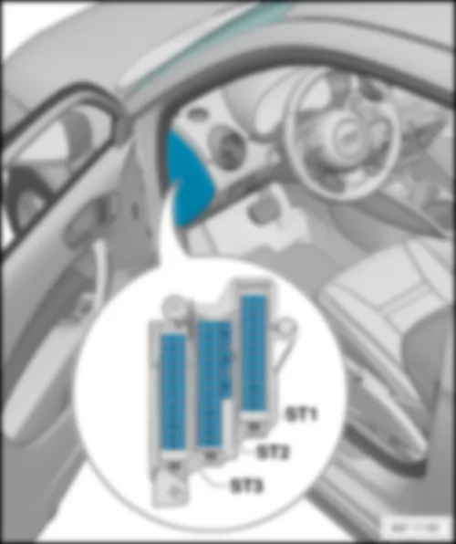
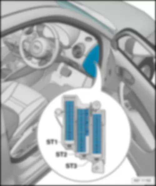
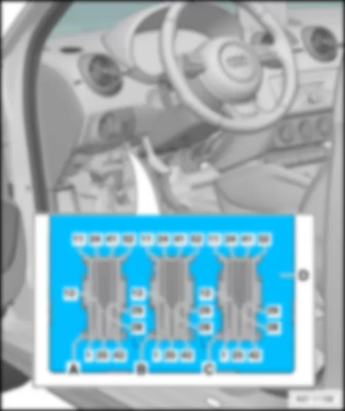
ST1 - | Fuse carrier 1, fuses → chapter |
ST2 - | Fuse carrier 2, fuses → chapter |
ST3 - | Fuse carrier 3, fuses → chapter |
Note
|
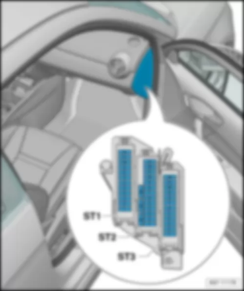
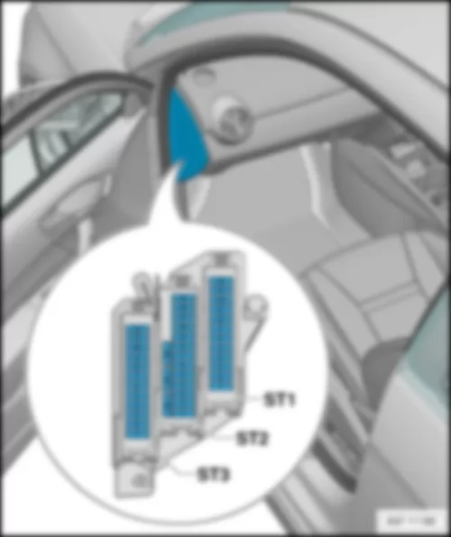
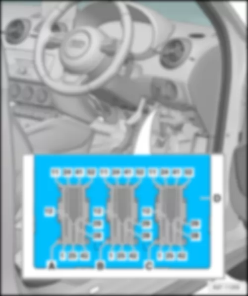
ST1 - | Fuse carrier 1, fuses → chapter |
ST2 - | Fuse carrier 2, fuses → chapter |
ST3 - | Fuse carrier 3, fuses → chapter |
|
Fuses in fuse carrier 1 -ST1- on fuse holder C -SC- (black) |
No. | Current Flow Diagram designation | Nominal value | Function/component | Terminal | ||
1 | - | Fuse 1 on fuse holder C -SC1- | 30 A | - | Digital sound package control unit -J525- Voltage stabiliser -J532- Radio -R- | 30 |
2 | - | Fuse 2 on fuse holder C -SC2- | 40 A | - | Heater control unit -J65- X-contact relief relay -J59- Fresh air blower control unit -J126- Fresh air blower -V2- | 30 |
3 | - | Fuse 3 on fuse holder C -SC3- | 20 A | - | Cigarette lighter -U1- 12 V socket -U5- | 15 |
4 | - | Fuse 4 on fuse holder C -SC4- | 15 A | - | Trailer detector control unit -J345- | 15 |
5 | - | Fuse 5 on fuse holder C -SC5- | 5 A | - | Data bus diagnostic interface -J533- | 30 |
6 | - | Fuse 6 on fuse holder C -SC6- | 30 A | - | Front passenger door control unit -J387- Rear right door control unit -J389- | 30 |
7 | - | Fuse 7 on fuse holder C -SC7- | 30 A | - | Driver door control unit -J386- Rear left door control unit -J388- | 30 |
8 | - | Fuse 8 on fuse holder C -SC8- | 30 A | - | Heated rear window relay -J9- Heated rear window -Z1- | 30 |
9 | - | Fuse 9 on fuse holder C -SC9- | 25 A | - | ABS control unit -J104- | 30 |
10 | - | Fuse 10 on fuse holder C -SC10- | 20 A | - | Onboard supply control unit -J519- | 30 |
11 | - | Fuse 11 on fuse holder C -SC11- | 15 A | - | High tone horn -H2- Low tone horn -H7- Horn relay -J413- | 30 |
12 | - | Fuse 12 on fuse holder C -SC12- | 30 A | - | Onboard supply control unit -J519- | 30 |
Fuses in fuse carrier 2 -ST2- on fuse holder C -SC- (brown) |
No. | Current Flow Diagram designation | Nominal value | Function/component | Terminal | ||
1 | - | Fuse 1 on fuse holder C -SC1- | 5 A | - | Alarm horn -H12- Anti-theft alarm sensor -G578- | 30 |
2 | - | Fuse 2 on fuse holder C -SC2- | 5 A → Note19) 5 A → Note16) 7.5 A → Note14) 7.5 A → Note15) 7.5 A → Note17) 7.5 A → Note18) 7.5 A → Note20) | - | Terminal 30 voltage supply relay -J317- → Note22) Motronic current supply relay -J271- → Note21) Engine control unit -J623- | 30 |
3 | - | Fuse 3 on fuse holder C -SC3- | 5 A | - | Onboard supply control unit -J519- | 30 |
4 | - | Fuse 4 on fuse holder C -SC4- | 5 A 15 A → Note23) | - | ABS control unit -J104- Voltage stabiliser 2 -J570- All-wheel drive control unit -J492- → Note23) | 30 |
5 | - | Fuse 5 on fuse holder C -SC5- | - | - | Vacant | - |
6 | - | Fuse 6 on fuse holder C -SC6- | 5 A | - | Light/rain sensor -G397- Aerial amplifier for mobile telephone -R86- Telephone bracket -R126- Front roof module -WX3- | 30 |
7 | - | Fuse 7 on fuse holder C -SC7- | 15 A → Note21) 20 A → Note22) | - | Fuel pump control unit -J538- → Note21) Fuel pump relay -J17- → Note22) | 30 |
8 | - | Fuse 8 on fuse holder C -SC8- | 10 A → Note21) | - | Auxiliary coolant pump relay -J496-, up to October 2014 | 30 |
9 | - | Fuse 9 on fuse holder C -SC9- | 5 A | - | Steering column electronics control unit -J527- | 30 |
10 | - | Fuse 10 on fuse holder C -SC10- | 5 A | - | Light switch -E1- | 30 |
11 | - | Fuse 11 on fuse holder C -SC11- | 10 A | - | Climatronic control unit -J255- Air conditioning system control unit -J301- Front passenger door control unit -J387- (up to April 2012) Rear right door control unit -J389- (up to April 2012) 16-pin connector -T16-, diagnosis connection | 30 |
12 | - | Fuse 12 on fuse holder C -SC12- | 10 A | - | Driver door control unit -J386- (up to April 2012) Rear left door control unit -J388- (up to April 2012) | 30 |
13 | - | Fuse 13 on fuse holder C -SC13- | 10 A | - | Onboard supply control unit -J519- | 30 |
14 | - | Fuse 14 on fuse holder C -SC14- | 20 A | - | Relay for power sockets -J807-, for models without trailer socket only | 30 |
15 | - | Fuse 15 on fuse holder C -SC15- | 30 A | - | Onboard supply control unit -J519- | 30 |
16 | - | Fuse 16 on fuse holder C -SC16- | 20 A | - | Wiper motor switch-over relay 1 -J368-, up to October 2014 Engine component current supply relay -J757- → Note23) → Note24) Ignition coil 1 with output stage -N70- → Note23) → Note24) Ignition coil 2 with output stage -N127- → Note23) → Note24) Ignition coil 3 with output stage -N291- → Note23) → Note24) Ignition coil 4 with output stage -N292- → Note23) → Note24) | 30 |
|
Fuses in fuse carrier 3 -ST3- on fuse holder C -SC- (red) |
No. | Current Flow Diagram designation | Nominal value | Function/component | Terminal | ||
1 | - | Fuse 1 on fuse holder C -SC1- | 5 A → Note30) 5 A → Note31) 20 A → Note26) 20 A → Note27) 20 A → Note28) | - | Automatic glow period control unit -J179- Vacuum pump for brakes -V192- | 15 |
2 | - | Fuse 2 on fuse holder C -SC2- | 10 A 5 A → Note34) | - | Brake light switch -F- (up to October 2011) brake pedal switch -F63- (up to October 2011) auxiliary coolant pump relay -J496- Lambda probe heater -Z19- (up to October 2011) Lambda probe 1 heater after catalytic converter -Z29-, (up to October 2011) Supply Fuse 9 on fuse holder F -SF9-, (from November 2011, up to October 2014) Supply Fuse 10 on fuse holder F -SF10- (from November 2011, up to October 2014) ABS control unit -J104-, from November 2011 | 15 |
3 | - | Fuse 3 on fuse holder C -SC3- | 5 A → Note29) 5 A → Note30) 5 A → Note31) 7.5 A → Note27) 15 A → Note25) 15 A → Note26) 15 A → Note28) | - | Air mass meter -G70-, up to October 2014 Fuel pump relay -J17-, up to October 2014 Low heat output relay -J359-, up to October 2014 High heat output relay -J360-, up to October 2014 Engine component current supply relay -J757-, up to October 2014 Fuel pressure regulating valve -N276-, up to October 2014 Coolant circulation pump -V50-, up to October 2014 | 15 |
4 | - | Fuse 4 on fuse holder C -SC4- | 15 A → Note25) 15 A → Note26) 15 A → Note28) 15 A → Note27) 25 A → Note29) 30 A → Note30) 30 A → Note31) | - | Engine control unit -J623- Clutch position sender -G476-, up to October 2011 Brake light switch -F-, up to October 2011 | 15 |
5 | - | Fuse 5 on fuse holder C -SC5- | 20 A → Note29) 15 A → Note30) 15 A → Note31) 20 A → Note25) 20 A → Note26) 20 A → Note28) 30 A → Note27) | - | Ignition coil 1 with output stage -N70-, up to October 2014 Ignition coil 2 with output stage -N127-, up to October 2014 Ignition transformer -N152-, up to October 2014 Fuel pressure regulating valve -N276-, up to October 2014 Fuel metering valve -N290-, up to October 2014 Ignition coil 3 with output stage -N291-, up to October 2014 Ignition coil 4 with output stage -N292-, up to October 2014 | 15 |
6 | - | Fuse 6 on fuse holder C -SC6- | 10 A 20 A → Note27) | - | Radiator fan control unit -J293-, up to October 2014 Heater element relay -J925-, up to October 2014 Charge pressure control solenoid valve -N75-, up to October 2014 Activated charcoal filter solenoid valve 1 -N80-, up to October 2014 Exhaust camshaft control valve 1 -N205-, up to October 2014 Recirculation valve for turbocharger -N249-, up to October 2014 Intake manifold flap valve -N316-, up to October 2014 Exhaust camshaft control valve 1 -N318-, up to October 2014 Switchover valve for exhaust recirculation cooler -N345-, up to October 2014 Oil pressure regulation valve -N428-, up to October 2014 Intake cam adjuster for cylinder 2 -N583-, up to October 2014 Exhaust cam adjuster for cylinder 2 -N587-, up to October 2014 Intake cam adjuster for cylinder 3 -N591-, up to October 2014 Exhaust cam adjuster for cylinder 3 -N595-, up to October 2014 Pump for exhaust recirculation cooler -V400- | 15 |
7 | - | Fuse 7 on fuse holder C -SC7- | 5 A | - | CD changer -R41- | 15 |
8 | - | Fuse 8 on fuse holder C -SC8- | 5 A | - | Internet access control unit -J666- Chip card reader control unit -J676- Radio -R- TV tuner -R78- | 15 |
9 | - | Fuse 9 on fuse holder C -SC9- | 5 A | - | Control unit in dash panel insert -J285- | 15 |
10 | - | Fuse 10 on fuse holder C -SC10- | 5 A | - | Relay for automatic anti-dazzle interior mirror -J910- Automatic anti-dazzle interior mirror -Y7- | 15 |
11 | - | Fuse 11 on fuse holder C -SC11- | 7.5 A → Note32) 15 A → Note33) | - | Radio -R- Control unit for information electronics 1 -J794- | 15 |
12 | - | Fuse 12 on fuse holder C -SC12- | 5 A | - | Display unit for front information display and operating unit control unit -J685- | 15 |
AUDI A1 2014 Fuse holder D SD
Note
|
ST1 - | Fuse carrier 1, fuses → chapter |
ST2 - | Fuse carrier 2, fuses → chapter |
ST3 - | Fuse carrier 3, fuses → chapter |
Note
|
ST1 - | Fuse carrier 1, fuses → chapter |
ST2 - | Fuse carrier 2, fuses → chapter |
ST3 - | Fuse carrier 3, fuses → chapter |
|
Fuses in fuse carrier 1 -ST1- on fuse holder D -SD- (black) |
No. | Current Flow Diagram designation | Nominal value | Function/component | Terminal | ||
1 | - | Fuse 1 on fuse holder D -SD1- | 7.5 A | - | ESL control unit -J764- | 30 |
2 | - | Fuse 2 on fuse holder D -SD2- | 20 A | - | Trailer detector control unit -J345- | 30 |
3 | - | Fuse 3 on fuse holder D -SD3- | 20 A | - | Trailer detector control unit -J345- | 30 |
4 | - | Fuse 4 on fuse holder D -SD4- | 30 A 7.5 A | - | Mechatronic unit for dual clutch gearbox -J743-, up to October 2014 Electronically controlled damping control unit -J250-, from January 2014 | 30 |
5 | - | Fuse 5 on fuse holder D -SD5- | 30 A | - | Headlight washer system relay -J39- Headlight washer system pump -V11- | 30 |
6 | - | Fuse 6 on fuse holder D -SD6- | 5 A | - | Interface control unit for vehicle location system -J843- | 30 |
7 | - | Fuse 7 on fuse holder D -SD7- | 7.5 A | - | Entry and start authorisation control unit -J518- | 30 |
8 | - | Fuse 8 on fuse holder D -SD8- | 15 A | - | Mechatronic unit for dual clutch gearbox -J743-, up to October 2014 | 30 |
9 | - | Fuse 9 on fuse holder D -SD9- | 20 A | - | Sliding sunroof motor -V1- | 30 |
10 | - | Fuse 10 on fuse holder D -SD10- | 7.5 A | - | Selector lever sensors control unit -J587- | 30 |
11 | - | Fuse 11 on fuse holder D -SD11- | 15 A → Note35) | - | Engine component current supply relay -J757-, up to October 2014 Fuel pressure regulating valve -N276- , up to October 2014 | 30 |
12 | - | Fuse 12 on fuse holder D -SD12- | - | - | Vacant | 30 |
|
Fuses in fuse carrier -ST2- on fuse holder D -SD- (brown) |
No. | Current Flow Diagram designation | Nominal value | Function/component | Terminal | ||
1 | - | Fuse 1 on fuse holder D -SD1- | 5 A | - | Reversing light switch -F4- Selector lever sensors control unit -J587- Mechatronic unit for dual clutch gearbox -J743- | 15 |
2 | - | Fuse 2 on fuse holder D -SD2- | 10 A | - | High-pressure sender -G65- Oil level and oil temperature sender -G266- Air conditioning system control unit -J301- Relay for power sockets -J807- Automatic anti-dazzle interior mirror -Y7- 16-pin connector -T16-, diagnosis connection | 15 |
3 | - | Fuse 3 on fuse holder D -SD3- | 5 A | - | Data bus diagnostic interface -J533- | 15 |
4 | - | Fuse 4 on fuse holder D -SD4- | 5 A | - | Heater control unit -J65- Control unit for structure-borne sound -J869- | 15 |
5 | - | Fuse 5 on fuse holder D -SD5- | 7.5 A | - | Light switch -E1- Starter relay 1 -J906- Voltage stabiliser -J532- Starter relay 2 -J907- Relay for automatic anti-dazzle interior mirror -J910- Front left headlight -MX1- Front right headlight -MX2- | 15 |
6 | - | Fuse 6 on fuse holder D -SD6- | 5 A | - | Light switch -E1- | 15 |
7 | - | Fuse 7 on fuse holder D -SD7- | 5 A | - | ABS control unit -J104-, up to October 2014 Voltage stabiliser 2 -J570-, up to October 2014 Electronically controlled damping control unit -J250-, from January 2014 | 15 |
8 | - | Fuse 8 on fuse holder D -SD8- | 5 A | - | Heated driver seat regulator -E94- Heated front passenger seat regulator -E95- Hazard warning lights button -E229- Heated rear window button -E230- TCS and ESP button -E256- Parking aid button -E266- Tyre pressure monitor display button -E492- Start/Stop operation button -E693- Trailer detector control unit -J345- Left washer jet heater element -Z20- Right washer jet heater element -Z21- | 15 |
9 | - | Fuse 9 on fuse holder D -SD9- | 5 A | - | Power steering control unit -J500- | 15 |
10 | - | Fuse 10 on fuse holder D -SD10- | 5 A → Note36) 7.5 A → Note37) | - | Air mass meter -G70- Fuel pump control unit -J538- Crankcase breather heater element -N79- | 15 |
11 | - | Fuse 11 on fuse holder D -SD11- | 5 A | - | Airbag control unit -J234- Front passenger airbag deactivated warning lamp -K145- | 15 |
12 | - | Fuse 9 on fuse holder D -SD12- | 5 A | - | Parking aid control unit -J446- | 15 |
13 | - | Fuse 10 on fuse holder D -SD13- | 5 A | - | Control unit for headlight range control -J431- | 15 |
14 | - | Fuse 9 on fuse holder D -SD14- | 30 A | - | Seat heating control unit -J882- | 15 |
15 | - | Fuse 10 on fuse holder D -SD15- | 15 A | - | Rear window wiper motor -V12- | 15 |
16 | - | Fuse 11 on fuse holder D -SD16- | 5 A | - | Engine control unit -J623- Air mass meter -G70- | 15 |
|
Fuses in fuse carrier -ST3- on fuse holder D -SD- (red) |
No. | Current Flow Diagram designation | Nominal value | Function/component | Terminal | ||
1 | - | Fuse 1 on fuse holder D -SD1- | - | Vacant | ||
2 | - | Fuse 2 on fuse holder D -SD2- | - | Vacant | ||
3 | - | Fuse 3 on fuse holder D -SD3- | 10 A | - | All-wheel drive control unit -J492- , gradual phase-out | 15 |
4 | - | Fuse 4 on fuse holder D -SD4- | - | Vacant | ||
5 | - | Fuse 5 on fuse holder D -SD5- | - | Vacant | ||
6 | - | Fuse 6 on fuse holder D -SD6- | - | Vacant | ||
7 | - | Fuse 7 on fuse holder D -SD7- | - | Vacant | ||
8 | - | Fuse 8 on fuse holder D -SD8- | - | Vacant | ||
9 | - | Fuse 9 on fuse holder D -SD9- | - | Vacant | ||
10 | - | Fuse 10 on fuse holder D -SD10- | 5 A 10 A | - | Special vehicle control unit -J608- | |
11 | - | Fuse 11 on fuse holder D -SD11- | - | Vacant | ||
12 | - | Fuse 12 on fuse holder D -SD12- | - | Vacant |
AUDI A1 2014 Relay/ fuse holder F SF
Note
|
SF1 - | Fuse 1 on fuse holder F → chapter |
SF2 - | Fuse 2 on fuse holder F → chapter |
SF3 - | Fuse 3 on fuse holder F → chapter |
SF4 - | Fuse 4 on fuse holder F → chapter |
SF5 - | Fuse 5 on fuse holder F → chapter |
SF6 - | Fuse 6 on fuse holder F → chapter |
16 - | Fuse 9 on fuse holder F -SF9- → Chapter |
17 - | Fuse 10 on fuse holder F -SF10- → Chapter |
Note
|
No. | Current Flow Diagram designation | Nominal value | Function/component | Terminal | ||
1 | - | Fuse 1 on fuse holder F -SF1- | 40 A | - | Voltage stabiliser -J532- | 30 |
2 | - | Fuse 2 on fuse holder F -SF2- | 50 A | - | Supply fuse carrier 1 -ST1- in fuse holder D -SD- | 30 |
3 | - | Fuse 3 on fuse holder F -SF3- | 40 A | - | Terminal 15 voltage supply relay -J329- | 30 |
4 | - | Fuse 4 on fuse holder F -SF4- | 40 A | - | ABS control unit -J104- | 30 |
5 | - | Fuse 5 on fuse holder F -SF5- | 5 A | - | Voltage stabiliser 2 -J570-, gradual phase-out | 30 |
6 | - | Fuse 6 on fuse holder F -SF6- | 5 A | - | Onboard supply control unit -J519- Voltage stabiliser -J532- Voltage stabiliser 2 -J570-, gradual phase-out Engine control unit -J623- | 30 |
16 | - | Fuse 9 on fuse holder F -SF9 (ab - (from November 2011) | 10 A | - | Brake light switch -F- (from November 2011, up to October 2014) Clutch position sender -G476- (from November 2011, up to November 2014) | 15 |
17 | - | Fuse 10 on fuse holder F -SF10- (from November 2011) | 5 A | - | Lambda probe heater -Z19- (from November 2011, up to October 2014) Lambda probe 1 heater after catalytic converter -Z29- (from November 2011, up to November 2014) | 15 |
AUDI A1 2014 Overview of control units in interior of vehicle (3-door models)
Overview of control units in interior of vehicle (3-door models)1 - | Fresh air blower control unit -J126- |
q | Location: in front passenger footwell, behind the glove compartment |
q | Overview of 5-door models → item |
2 - | CD changer -R41- |
q | for models with MMI |
q | Fitting location and connectors: → chapter |
q | for models with radio chorus or concert: → item |
q | Overview of 5-door models → item |
3 - | Entry and start authorisation control unit -J518- |
q | Fitting location and connector: → chapter |
q | Overview of 5-door models → item |
3 - | Parking aid control unit -J446- |
q | Fitting location and connectors: → chapter |
q | Overview of 5-door models → item |
3 - | Aerial amplifier for mobile telephone -R86- |
q | Fitting location and connectors: → chapter |
q | Overview of 5-door models → item |
3 - | Seat heating control unit -J882- |
q | Fitting location and connector: → chapter |
q | Overview of 5-door models → item |
4 - | Control unit for headlight range control -J431- |
q | Fitting location and connectors: → chapter |
q | Overview of 5-door models → item |
5 - | Display unit for front information display and operating unit control unit -J685- |
q | Location: in middle part dash panel |
q | Overview of 5-door models → item |
6 - | Front passenger door control unit -J387- |
q | Fitting location and connectors for models with left-hand drive: → chapter |
q | Fitting location and connectors for models with right-hand drive: → anchor |
q | Overview of 5-door models → item |
7 - | Voltage stabiliser -J532- |
q | Fitting location and connector: → chapter |
q | Overview of 5-door models → item |
8 - | Driver door control unit -J386- |
q | Fitting location and connectors for models with left-hand drive: → chapter |
q | Fitting location and connectors for models with right-hand drive: → anchor |
q | Overview of 5-door models → item |
9 - | Multifunction steering wheel control unit -J453- |
q | Location: on steering column |
q | Overview of 5-door models → item |
9 - | Steering column electronics control unit -J527- |
q | Location: on steering column |
q | Overview of 5-door models → item |
9 - | ESL control unit -J764- |
q | Fitting location and connector: → chapter |
q | Overview of 5-door models → item |
9 - | Immobiliser reader coil -D2- |
q | Fitting location and connector for models with ignition lock: → chapter |
q | Fitting location and connector for models without ignition lock (with keyless entry system): → anchor |
q | Overview of 5-door models → item |
10 - | Control unit in dash panel insert -J285- |
q | Location: in driver side dash panel |
q | Overview of 5-door models → item |
11 - | 16-pin connector -T16-, diagnosis connection |
q | Fitting location for models with left-hand drive: → chapter |
q | Fitting location for models with right-hand drive: → anchor |
q | Overview of 5-door models → item |
12 - | Onboard supply control unit -J519- |
q | Fitting location and connectors for models with left-hand drive: → chapter |
q | Fitting location and connectors for models with right-hand drive: → anchor |
q | Overview of 5-door models → item |
13 - | Data bus diagnostic interface -J533- |
q | Fitting location and connector for models with left-hand drive: → chapter |
q | Fitting location and connector for models with right-hand drive: → anchor |
q | Overview of 5-door models → item |
14 - | Airbag control unit -J234- |
q | Fitting location and connector: → chapter |
q | Overview of 5-door models → item |
15 - | Control unit for information electronics 1 -J794- |
q | for models with MMI |
q | Location: in middle part dash panel |
15 - | Radio -R- |
q | for models with radio chorus or concert |
q | Location: in middle part dash panel |
q | Fitting location for models with MMI: → item |
q | Overview of 5-door models → item |
15 - | CD changer -R41- |
q | for models with radio chorus or concert |
q | Location: in middle part dash panel (integrated in radio) |
q | Overview of 5-door models → item |
15 - | Heater control unit -J65- |
q | for models with heater (without air conditioning) |
q | Location: at bottom of middle part dash panel |
q | Overview of 5-door models → item |
15 - | Climatronic control unit -J255- |
q | for models with automatic air conditioning system |
q | Location: at bottom of middle part dash panel |
q | Overview of 5-door models → item |
15 - | Air conditioning system control unit -J301- |
q | for models with manual air conditioning system |
q | Location: at bottom of middle part dash panel |
q | Overview of 5-door models → item |
AUDI A1 2014 Overview of control units in interior of vehicle (5-door models)
Overview of control units in interior of vehicle (5-door models) |
1 - | Fresh air blower control unit -J126- |
q | Location: in front passenger footwell, behind the glove compartment |
2 - | CD changer -R41- |
q | for models with MMI |
q | Fitting location and connectors: → chapter |
q | for models with radio chorus or concert: → item |
3 - | Entry and start authorisation control unit -J518- |
q | Fitting location and connector: → chapter |
3 - | Parking aid control unit -J446- |
q | Fitting location and connectors: → chapter |
3 - | Aerial amplifier for mobile telephone -R86- |
q | Fitting location and connectors: → chapter |
3 - | Seat heating control unit -J882- |
q | Fitting location and connector: → chapter |
4 - | Control unit for headlight range control -J431- |
q | Fitting location and connectors: → chapter |
5 - | Display unit for front information display and operating unit control unit -J685- |
q | Location: in middle part dash panel |
6 - | Front passenger door control unit -J387- |
q | Fitting location and connectors for models with left-hand drive: → chapter |
q | Fitting location and connectors for models with right-hand drive: → anchor |
7 - | Voltage stabiliser -J532- |
q | Fitting location and connector: → chapter |
8 - | Rear right door control unit -J389- |
q | Location: in rear right door |
9 - | Rear left door control unit -J388- |
q | Location: in rear left door |
10 - | Driver door control unit -J386- |
q | Fitting location and connectors for models with left-hand drive: → chapter |
q | Fitting location and connectors for models with right-hand drive: → anchor |
11 - | Multifunction steering wheel control unit -J453- |
q | Location: on steering column |
11 - | Steering column electronics control unit -J527- |
q | Location: on steering column |
11 - | ESL control unit -J764- |
q | Fitting location and connector: → chapter |
11 - | Immobiliser reader coil -D2- |
q | Fitting location and connector for models with ignition lock: → chapter |
q | Fitting location and connector for models without ignition lock (with keyless entry system): → anchor |
12 - | Control unit in dash panel insert -J285- |
q | Location: in driver side dash panel |
13 - | 16-pin connector -T16-, diagnosis connection |
q | Fitting location for models with left-hand drive: → chapter |
q | Fitting location for models with right-hand drive: → anchor |
14 - | Onboard supply control unit -J519- |
q | Fitting location and connectors for models with left-hand drive: → chapter |
q | Fitting location and connectors for models with right-hand drive: → anchor |
15 - | Data bus diagnostic interface -J533- |
q | Fitting location and connector for models with left-hand drive: → chapter |
q | Fitting location and connector for models with right-hand drive: → anchor |
16 - | Airbag control unit -J234- |
q | Fitting location and connector: → chapter |
17 - | Radio -R- |
q | for models with radio chorus or concert |
q | Location: in middle part dash panel |
q | Fitting location for models with MMI: → item |
17 - | CD changer -R41- |
q | for models with radio chorus or concert |
q | Location: in middle part dash panel (integrated in radio) |
17 - | Heater control unit -J65- |
q | for models with heater (without air conditioning) |
q | Location: at bottom of middle part dash panel |
17 - | Climatronic control unit -J255- |
q | for models with automatic air conditioning system |
q | Location: at bottom of middle part dash panel |
17 - | Air conditioning system control unit -J301- |
q | for models with manual air conditioning system |
q | Location: at bottom of middle part dash panel |
Note
|
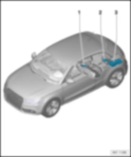
1 - | Fuel pump control unit -J538- |
q | Fitting location and connectors: → chapter |
2 - | Battery monitor control unit -J367- |
q | for models with battery in luggage compartment |
q | Fitting location and connector: → chapter |
q | for models with battery in engine compartment: location in engine compartment at battery negative terminal |
3 - | Control units on left in luggage compartment: → chapter |
3 - | Digital sound package control unit -J525- |
q | Fitting location and connectors: → chapter |
3 - | Radio -R- |
q | for models with MMI |
q | Fitting location and connectors: → chapter |
q | Fitting location for models with radio chorus or concert (without MMI): → item |
3 - | TV tuner -R78- |
q | Fitting location and connectors: → chapter |
3 - | TV card reader -R204- |
q | Fitting location and connector: → chapter |
3 - | Trailer detector control unit -J345- |
q | Location: in left of luggage compartment, behind side trim. |
AUDI A1 2014 CD changer R41
|
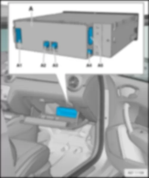
A - | CD changer -R41- |
A1 - | 2-pin connector (connector B) -T2dm- |
A2 - | Vacant |
A3 - | Vacant |
A4 - | Vacant |
A5 - | 8-pin connector, black (connector A) -T8aa- |
AUDI A1 2014 Control unit for headlight range control J431
|
A - | Control unit for headlight range control -J431- |
B - | 26-pin connector, black -T26a- |
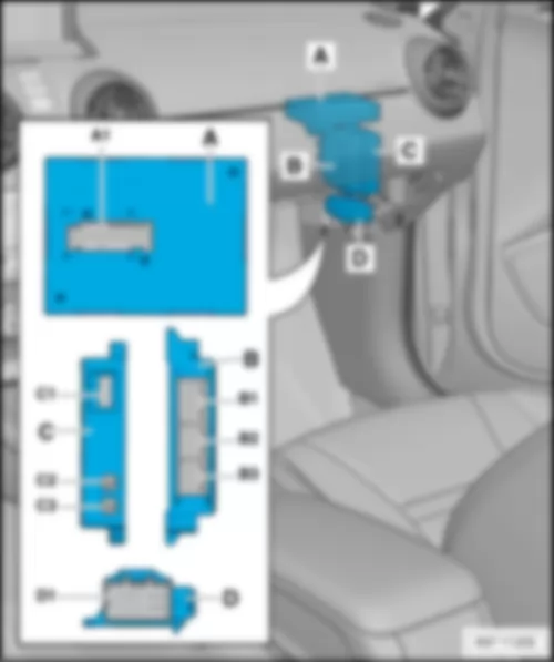
AUDI A1 2014 Control units at instrument panel, front passenger side
|
A - | Entry and start authorisation control unit -J518- |
A1 - | 32-pin connector, blue -T32- |
B - | Parking aid control unit -J446- |
B1 - | 16-pin connector, brown -T16e- |
B2 - | 12-pin connector, brown -T12e- |
B3 - | 12-pin connector, black -T12g- |
C - | Aerial amplifier for mobile telephone -R86- |
C1 - | 4-pin connector, black -T4ak- |
C2 - | 1-pin connector, black -T1v- |
C3 - | 1-pin connector, violet -T1u- |
D - | Seat heating control unit -J882- |
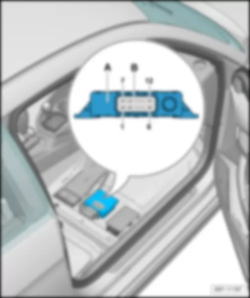
D1 - | 16-pin connector, black -T16b- |
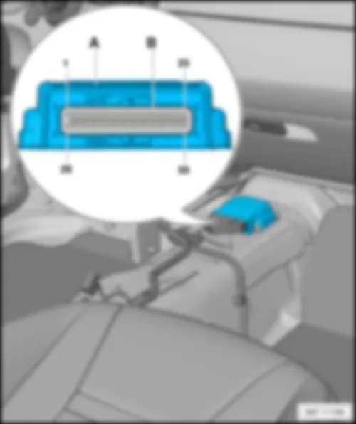
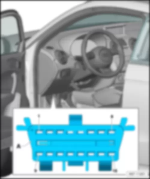
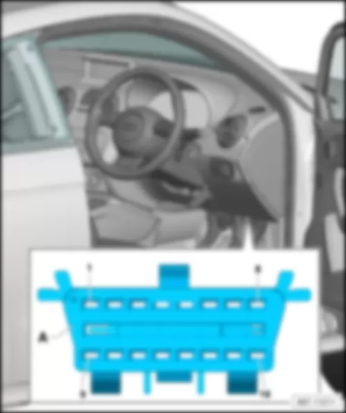
AUDI A1 2014 Airbag control unit J234
|
A - | Airbag control unit -J234- |
B - | 50-pin connector, yellow -T50- |
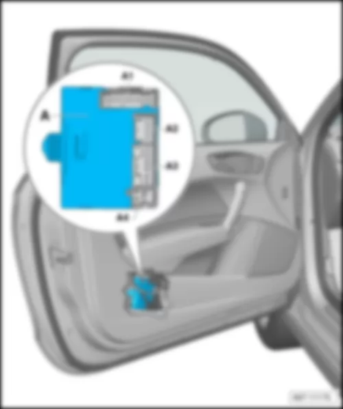
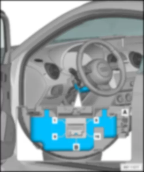
AUDI A1 2014 Driver door control unit J386
Note
|
A - | Driver door control unit -J386- |
A1 - | 32-pin connector -T32j- |
A2 - | 16-pin connector -T16m- |
A3 - | 20-pin connector -T20f- |
A4 - | 6-pin, connector -T6am- |
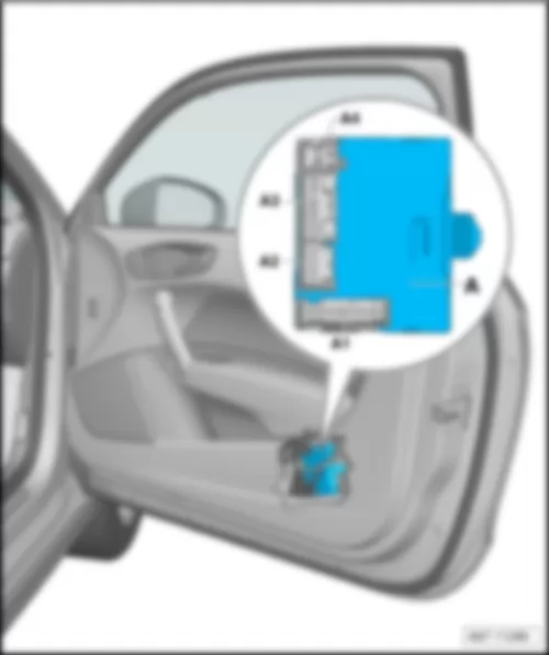
Note
|
A - | Driver door control unit -J386- |
A1 - | 32-pin connector -T32j- |
A2 - | 16-pin connector -T16m- |
A3 - | 20-pin connector -T20f- |
A4 - | 6-pin, connector -T6am- |
AUDI A1 2014 Front passenger door control unit J387
Note
|
A - | Front passenger door control unit -J387- |
A1 - | 32-pin connector -T32l- |
A2 - | 16-pin connector -T16n- |
A3 - | 20-pin connector -T20g- |
A4 - | 6-pin, connector -T6ao- |
Note
|
A - | Front passenger door control unit -J387- |
A1 - | 32-pin connector -T32l- |
A2 - | 16-pin connector -T16n- |
A3 - | 20-pin connector -T20g- |
A4 - | 6-pin, connector -T6ao- |
AUDI A1 2014 Voltage stabiliser J532
|
A - | Voltage stabiliser -J532- |
B - | 12-pin connector, black -T12aa- |
AUDI A1 2014 ESL control unit J764
Note
|
A - | ESL control unit -J764- |
B - | 16-pin connector -T16a- |
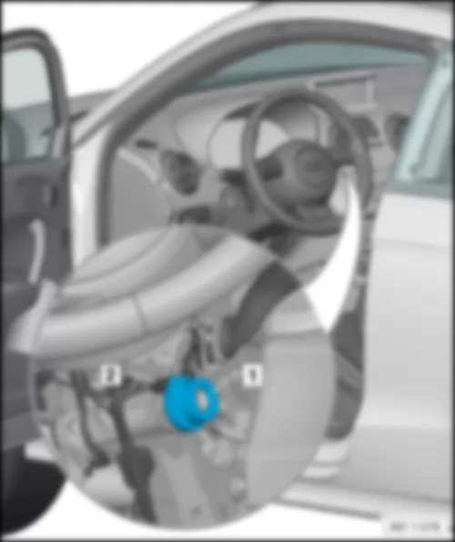
AUDI A1 2014 Immobiliser reader coil D2
Note
|
1 - | Immobiliser reader coil -D2- |
2 - | 2-pin connector -T2l- |
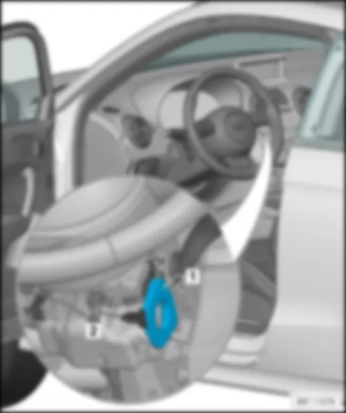
Note
|
1 - | Immobiliser reader coil -D2- |
2 - | 2-pin connector -T2l- |
AUDI A1 2014 Diagnosis connection - 16-pin connector T16
Note
|
A - | 16-pin connector -T16- |
Note
|
A - | 16-pin connector -T16- |
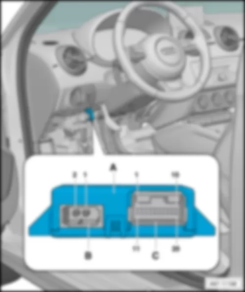
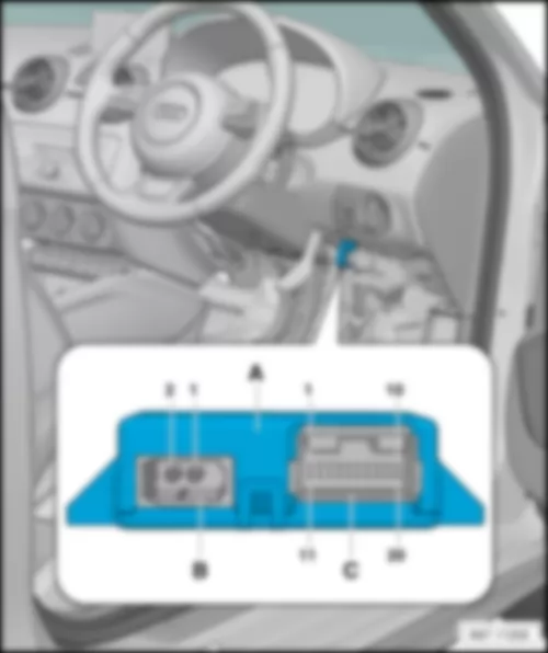
AUDI A1 2014 Data bus diagnostic interface J533
Note
|
A - | Data bus diagnostic interface -J533- |
B - | 2-pin connector, black -T2dl- |
C - | 20-pin connector, black -T20d- |
Note
|
A - | Data bus diagnostic interface -J533- |
B - | 2-pin connector, black -T2dl- |
C - | 20-pin connector, black -T20d- |
AUDI A1 2014 Onboard supply control unit J519
Note
|
D - | Onboard supply control unit -J519- |
A - | 52-pin connector, black (connector A) -T52a- |
B - | 52-pin connector, white (connector B) -T52b- |
C - | 52-pin connector, brown (connector C) -T52c- |
Note
|
D - | Onboard supply control unit -J519- |
A - | 52-pin connector, black (connector A) -T52a- |
B - | 52-pin connector, white (connector B) -T52b- |
C - | 52-pin connector, brown (connector C) -T52c- |
AUDI A1 2014 Fuel pump control unit J538
Note
|
A - | Fuel pump control unit -J538- |
A1 - | 10-pin connector -T10d- |
B1 - | 5-pin connector -T5a- |
AUDI A1 2014 Battery monitor control unit J367
Note
|
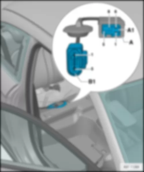
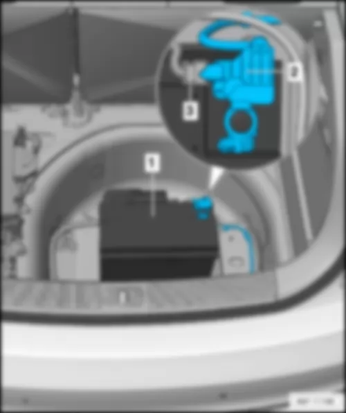
1 - | battery -A- |
2 - | Battery monitor control unit -J367- |
3 - | 2-pin connector, black -T2x- |
AUDI A1 2014 Control units on left in luggage compartment
|
A - | Digital sound package control unit -J525- |
A1 - | 2-pin connector, black -T2dk- |
A2 - | Vacant |
A3 - | 38-pin connector, black -T38- |
B - | TV tuner -R78- |
B1 - | 2-pin connector, brown -T2dh- |
B2 - | 2-pin connector, green -T2dn- |
B3 - | Single connector, green -T1m- |
B4 - | 2-pin connector, black -T2do- |
B5 - | 4-pin connector, blue -T4ah- |
B6 - | 20-pin connector, black -T20c- |
C - | Radio -R- |
C1 - | 2-pin connector -T2df- |
C2 - | 2-pin connector -T2dg- |
C3 - | Single connector -T1i- (for digital radio - DAB) |
C3 - | Single connector -T1l- (for satellite radio - SDARS) |
C4 - | Black connection block (-T8ag-, -T10ag-, -T12w-) |
D - | TV card reader -R204- |
- | 4-pin connector, blue -T4ai- |
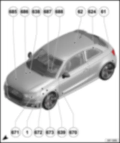
AUDI A1 2014 Overview of earth points
Overview of earth points Note
Overview also valid for 5-door models! |
685 | Earth point 1 on front right longitudinal member |
q | Fitting location: → anchor |
686 | Earth point 2 on front right longitudinal member |
q | Fitting location: → anchor |
638 | Earth point on right A-pillar |
q | Fitting location: → anchor |
687 | Earth point 1 on centre tunnel |
q | Fitting location: → anchor |
688 | Earth point 2 on centre tunnel |
q | Fitting location: → anchor |
62 | Earth point, right C-pillar |
q | Fitting location: → anchor |
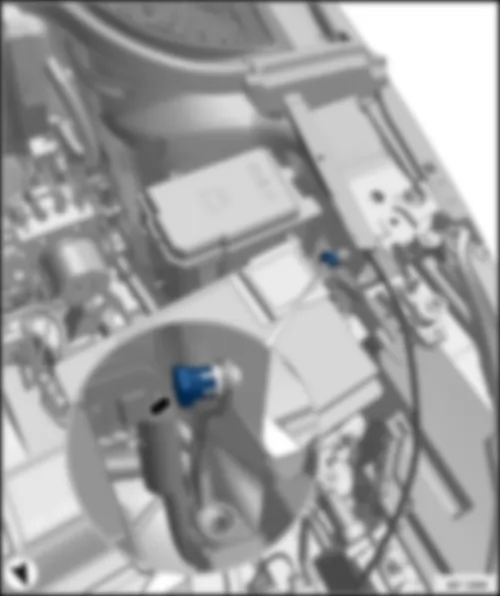
624 | Earth point next to starter battery |
q | Fitting location: → anchor |
61 | Earth point, left C-pillar |
q | Fitting location: → anchor |
670 | Earth point 2, left A-pillar |
q | Fitting location: → Anchor |
639 | Earth point on left A-pillar |
q | Fitting location: → anchor |
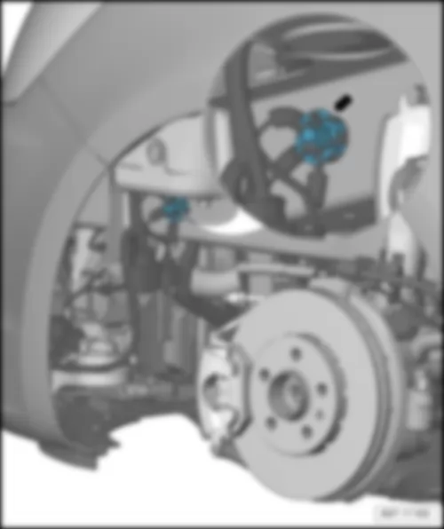
673 | Earth point 3 on front left longitudinal member |
q | Fitting location: → anchor |
672 | Earth point 2 on front left longitudinal member |
q | Fitting location: → anchor |
1 | Earth strap, battery - body |
q | Fitting location: → anchor |
671 | Earth point 1 on front left longitudinal member |
q | Fitting location: → anchor |
|
|
|
|
|
|
|
|
|
|
|
|