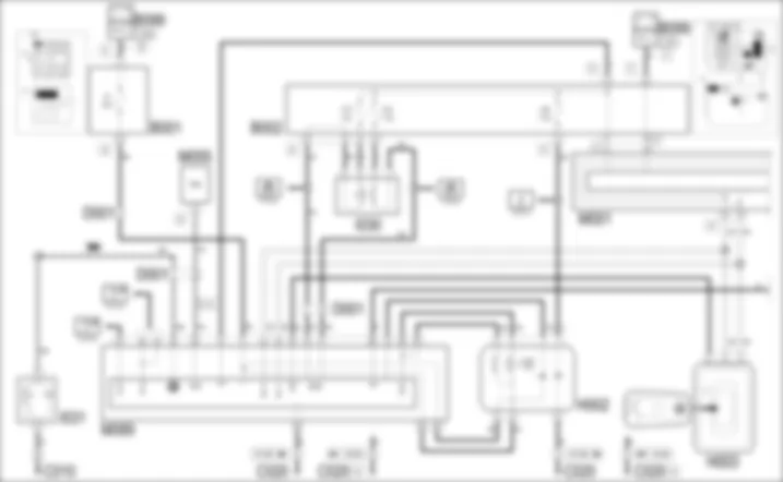

WIRING DIAGRAM - STARTING AND RECHARING - Alfa Romeo 159 1.9 JTD 16V Da 01/06
COMPONENTS - STARTING AND RECHARING - Alfa Romeo 159 1.9 JTD 16V Da 01/06
| Component code | Description | Reference to the operation |
| A001 | BATTERY | |
| A010 | ALTERNATOR | |
| A020 | STARTER MOTOR | |
| B001 | JUNCTION UNIT | |
| B002 | JUNCTION UNIT UNDER DASHBOARD | |
| B099 | MAXIFUSE BOX ON BATTERY | |
| C010 | LEFT FRONT EARTH | - |
| C015 | DASHBOARD EARTH, DRIVER'S SIDE | - |
| C020 | PASSENGER SIDE DASHBOARD EARTH | - |
| D001 | FRONT/DASHBOARD COUPLING | - |
| D004 | FRONT/ENGINE COUPLING | - |
| D006 | FRONT/REAR COUPLING | - |
| D029 | ENGINE CABLES/ENGINE SERVICES CABLE COUPLING | - |
| E050 | INSTRUMENT PANEL | |
| H002 | STARTING PUSH BUTTON | |
| H003 | IGNITION DEVICE | |
| I030 | BRAKE PEDAL SWITCH | |
| I031 | CLUTCH PEDAL SWITCH | |
| I050 | INERTIA SWITCH | |
| M001 | BODY COMPUTER | |
| M055 | AUTOMATIC TRANSMISSION CONTROL UNIT | - |
| M089 | STEERING LOCK CONTROL UNIT (NBS) | |
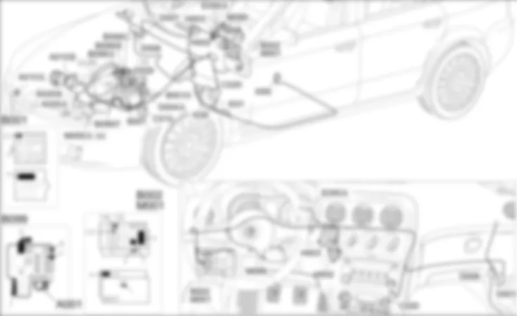
COMPONENT LOCATION - STARTING AND RECHARING - Alfa Romeo 159 1.9 JTD 16V Da 01/06
| Component code | Description | Reference to the operation |
| A001 | BATTERY | |
| A010 | ALTERNATOR | |
| A020 | STARTER MOTOR | |
| B001 | JUNCTION UNIT | |
| B002 | JUNCTION UNIT UNDER DASHBOARD | |
| B099 | MAXIFUSE BOX ON BATTERY | |
| C010 | LEFT FRONT EARTH | - |
| C015 | DASHBOARD EARTH, DRIVER'S SIDE | - |
| C020 | PASSENGER SIDE DASHBOARD EARTH | - |
| D001 | FRONT/DASHBOARD COUPLING | - |
| D004 | FRONT/ENGINE COUPLING | - |
| D006 | FRONT/REAR COUPLING | - |
| D029 | ENGINE CABLES/ENGINE SERVICES CABLE COUPLING | - |
| E050 | INSTRUMENT PANEL | |
| H002 | STARTING PUSH BUTTON | |
| H003 | IGNITION DEVICE | |
| I030 | BRAKE PEDAL SWITCH | |
| I031 | CLUTCH PEDAL SWITCH | |
| I050 | INERTIA SWITCH | |
| M001 | BODY COMPUTER | |
| M055 | AUTOMATIC TRANSMISSION CONTROL UNIT | - |
| M089 | STEERING LOCK CONTROL UNIT (NBS) | |
DESCRIPTION - STARTING AND RECHARING - Alfa Romeo 159 1.9 JTD 16V Da 01/06
The ignition and recharging circuit comprises the battery, starter motor and alternator.The starter motor consists of a d.c. motor supplied by the battery and an excitation electromagnet.769This vehicle is equipped with a starting system known as Smart-Key, whereby the traditional ignition key has been replaced with an electronic key "T.E.G.", (Transmitter for Entry and Go), combined with an electronic key reader and TEG-Reader radio frequency receiver.The vehicle is not started by inserting the key and turning it in the ignition switch (which is not present), but by inserting the TEG in the TEG Reader and operating the START/STOP button.Pressing the START button supplies the motor windings producing electromagnetic forces that rotate the actual motor pinion. This simultaneously activates the electromagnet that operates the mechanism that causes the pinion to mesh with the flywheel ring gear and thus turn the crankshaft.The alternator recharges the battery during normal engine rotation. The alternator shaft (rotor) is turned by the crankshaft via a belt. When supplied by an excitation current, the rotor generates a magnetic field that sets up an alternating current in the fixed winding (stator). A diode rectifier bridge at the back of the alternator allows the alternating current to be transformed into a direct current that is sent to recharge the battery.A voltage governor, also built into the alternator, maintains the power supply at a constant voltage (14 V) throughout all load variation and engine speed ranges.The efficiency of the recharging system is controlled by the Body Computer which measures the D+ signal coming from the alternator with the engine moving (revs above 700 rpm).If the voltage measured is insufficient, the warning light in the instrument panel is switched on as well as the display of a message.The fuse box on the battery includes an automatic battery disconnection device that, in emergencies, cuts off the supply to the engine starting/recharging lead.This interruption is controlled by the inertia switch in the same way as for the fuel pump.
FUNCTIONAL DESCRIPTION - STARTING AND RECHARING - Alfa Romeo 159 1.9 JTD 16V Da 01/06
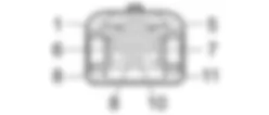
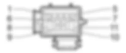
The START/STOP button H2 receives a power supply - pins 3 and 5 - from the steering lock control unit M89, which "relays" the direct power supply coming - at pin C1 of M89 - from the line protected by fuse F3 of the engine compartment junction unit B1.The lighting for the button is guaranteed by the ignition-controlled line (INT) protected by fuse F49 of the junction unit under the dashboard B2.When the button is pressed, "AVV" signals are sent from pins 4 and 6 of H2 to M89 - pins B6 and B7; tha latter supplies the electromagnet winding - from pin B8 - pin 50 of the starter motor A20 - connector B.767The supply and control signals for button H2 are "redundant" (two identical duplicate signals) for safety reasons, the wish of the user is recognized by means of the presence of only one of the two signals.The steering lock control unit M89 provides this power supply after a series of controls and checks.In particular, the TEG inserted status is sent by the TEG Reader H3 via the CAN - pins 3 and 8.The same signal is sent in a redundant manner to the steering lock node M89, form pin 2, and the latter, in turn, forwards it via the CAN.The starting go ahead only takes place if the clutch or the brake pedal is pressed: the control unit M89 receives the signal coming from the clutch switch I31 at pin A5 and the two brake pedal signals I30; the N.A. contact (pedal pressed) at pin C4 of M89 and the N.C. contact (pedal released) at pin C7 of M89.On versions with automatic transmission, when the gearbox is not in Park or Neutral, the starting of the vehicle is inhibited: a signal is sent from pin 5 of connector A of the automatic transmission control unit M55 to pin B4 of the steering lock control unit M89.Pin 30 of A20 - connector A - i.e. the actual motor, receives a power supply with the voltage coming directly from the battery A1.The continuous current produced by the alternator A10 (pin B+) - connector B - is sent to the battery A1, passing through the motor A20.These two lines are always supplied and not protected by fuses; they are however controlled by the automatic "battery disconnection" device located in the fuse box on the battery B99: if the inertia switch I50 intervenes, a signal is sent to connector F of B99 which "opens" the device, thereby removing the power supply from the motor A20 and the alternator A10.When the alternator does not turn and therefore does not recharge the battery, an earth signal is sent from pin D+ - connector A - of A10 to the Body Computer M1 - pin 19 of connector A: this is connected via the CAN line to the instrument panel E50 and manages the switching on of the recharging warning light in the instrument panel as described above. BATTERY
A001B
ALTERNATOR
A010A
A010A
A010A
A010A
A010B
A010B
A010B
STARTER MOTOR
A020A
A020A
A020A
A020B
A020B
A020B
A020B
JUNCTION UNIT
B001A
B001A
B001B
B001C
B001C
B001C
B001C
B001C
B001D
B001E
B001E
B001E
B001E
B001X
JUNCTION UNIT UNDER DASHBOARD
B002A
B002A
B002A
B002A
B002A
B002A
B002A
B002B
B002C
B002D
B002D
B002D
B002D
B002D
B002D
B002G
B002H
B002H
MAXIFUSE BOX ON BATTERY
B099A
B099A
B099B
B099C
B099E
B099F
LEFT FRONT EARTH
C010
C010
C010
DASHBOARD EARTH, DRIVER'S SIDE
C015
C015
C015
PASSENGER SIDE DASHBOARD EARTH
C020
C020A
C020B
FRONT/DASHBOARD COUPLING
D001
D001
D001
D001
D001
FRONT/ENGINE COUPLING
D004A
D004A
D004A
D004A
D004A
D004A
D004A
FRONT/REAR COUPLING
D006
D006
D006
ENGINE CABLES/ENGINE SERVICES CABLE COUPLING
D029
D029
INSTRUMENT PANEL
E050A
E050B
E050C
E050D
STARTING PUSH BUTTON
H002
H002
IGNITION DEVICE
H003
H003
BRAKE PEDAL SWITCH
I030
I030
I030
CLUTCH PEDAL SWITCH
I031
I031
I031
INERTIA SWITCH
I050
BODY COMPUTER
M001A
M001A
M001A
M001B
M001B
M001B
M001B
M001B
M001B
M001D
M001D
M001D
M001D
M001D
M001D
M001E
M001E
M001E
M001E
M001G
M001H
M001I
M001I
AUTOMATIC TRANSMISSION CONTROL UNIT
M055A
M055B
STEERING LOCK CONTROL UNIT (NBS)
M089
M089


 English
