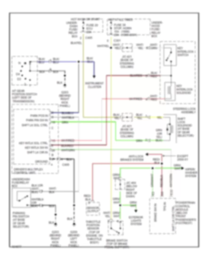
SHIFT INTERLOCK
Shift Interlock Wiring Diagram for Acura 3.5RL 1998
List of elements for Shift Interlock Wiring Diagram for Acura 3.5RL 1998:
- (1998) (1999-2001)
- (top of engine, on throttle body)
- A/t gear position switch (left side of
- Anti-lock brakes system
- Brake sw in
- Brake switch (top of brake pedal support)
- C301
- C405
- C406
- Driver's multiplex control unit
- E22
- Except 2000-01
- Exterior lights system
- Fuse 20 ecu 20a
- Fuse 39 stop, horn 15a 20a
- G200 (behind left kick panel)
- G203 (behind right kick panel)
- Ground
- Hot at all times
- Hot in on or start
- Instrument cluster
- J/c 421 (base of steering column)
- J/c 464 (below right side of dash)
- Key interlock solenoid
- Key interlock switch
- Key intlk sol ctrl
- Key intlk sw in
- Park pin sw in
- Park pos in
- Parking pin switch (at base of gear selector)
- Powertrain control module (below front passenger's footrest)
- Sensor output
- Shft lk cir ctrl
- Shft lk cir in
- Shft lk sol ctrl
- Shift lock solenoid (at base of gear selector)
- Steering lock assembly
- Throttle position sensor
- Tps in
- Transmission)
- Under- dash fuse/ relay box
- Under- hood fuse/ relay box
- Underdash fuse/relay box
- Wiper/ washer system
 Русский