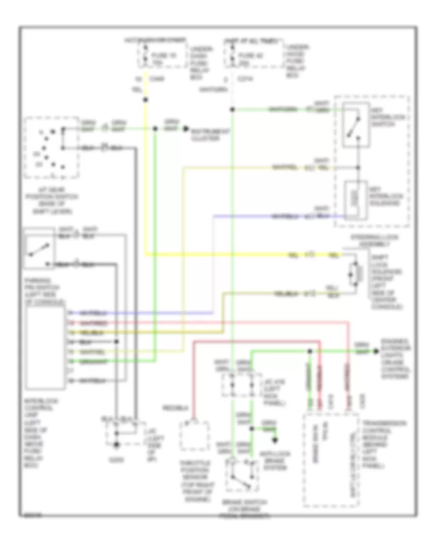
SHIFT INTERLOCK
Shift Interlock Wiring Diagram for Acura Integra GS-R 1997
List of elements for Shift Interlock Wiring Diagram for Acura Integra GS-R 1997:
- (left side of dash, above fuse/ relay box)
- (top right front of engine)
- A/t gear position switch (base of
- A18
- Anti-lock brake system
- Brake sw in
- Brake switch (on brake pedal bracket)
- C214
- C419
- C420
- C440
- Engines, exterior lights, cruise control, systems
- Fuse 15 10a
- Fuse 42 20a
- G202
- Hot at all times
- Hot in on or start
- Instrument cluster
- Interlock control unit
- J/c (left side of i/p)
- J/c 418 (left kick panel)
- Key interlock solenoid
- Key interlock switch
- Parking pin switch (left side of console)
- Shft lk cir rly ctrl
- Shift lever)
- Shift lock solenoid (front left side of center console)
- Steering lock assembly
- Throttle position sensor
- Tps in
- Transmission control module (behind left kick panel)
- Under- dash fuse/ relay box
- Under- hood fuse/ relay box
 English