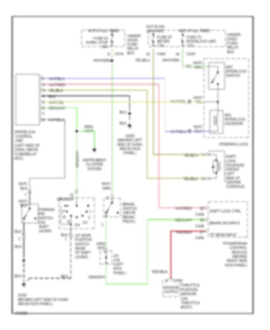
SHIFT INTERLOCK
Shift Interlock Wiring Diagram for Acura Integra GS-R 2000
List of elements for Shift Interlock Wiring Diagram for Acura Integra GS-R 2000:
- (left side of dash, above fuse/relay box)
- (on throttle body)
- A/t gear position switch (base of shift lever)
- Brake sw input
- Brake switch (above brake pedal)
- C115
- C216
- C408
- C409
- C439
- C440
- Fuse 25 meter 7.5a
- Fuse 33 interlock unit 7.5a
- Fuse 52 horn, stop 20a
- G202 (behind left side of dash, above kick panel)
- Hot at all times
- Hot in on or start
- Instrument cluster system
- Interlock control unit
- J/c (left kick panel)
- Key interlock solenoid
- Key interlock switch
- Parking pin switch (on shift lever)
- Powertrain control module (behind right side kick panel)
- Sensor output
- Shift lock ctrl
- Shift lock solenoid (front left side of center console)
- Steering lock
- Throttle position sensor
- Tp sens input
- Under- dash fuse/ relay box
- Under- hood fuse/ relay box
 English