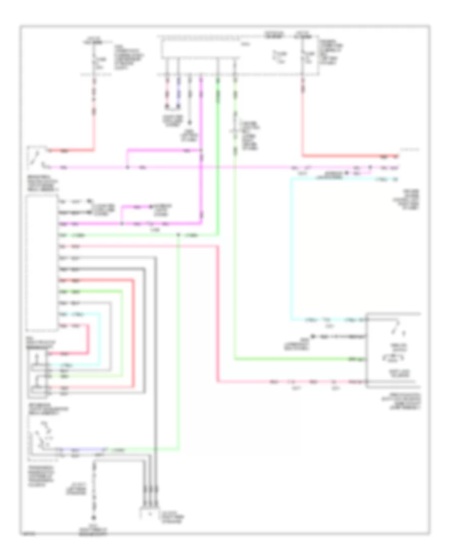
SHIFT INTERLOCK
Shift Interlock Wiring Diagram for Acura MDX 2014
List of elements for Shift Interlock Wiring Diagram for Acura MDX 2014:
- A10
- A25
- A27
- A37
- A41
- A42
- A43
- A44
- A45
- A46
- App sensor (top of accelerator pedal assembly)
- B11
- B19
- Brake pedal position switch (top of brake pedal assembly)
- C211
- C213
- C217
- C405
- C411
- Center junction box (upper right center of dash)
- Computer data lines system
- Driver's under-dash fuse/relay box (left end of dash)
- Exterior lights system
- Fuse 10a
- Fuse 20a
- Fuse 7.5a
- G101 (right rear of engine compt)
- G502 (left end of dash)
- G506 (upper right end of dash)
- H10
- Hot at all times
- Hot on on or start
- J/c c015 (right rear of engine)
- J/c c017 (left rear of engine)
- Keyless access control unit (right side of dash)
- Main under-hood fuse/relay box (center rear of engine compt)
- Micu
- Park pin switch
- Park pin switch/ shift lock solenoid (base of shift lever assembly)
- Pcm (right front of engine compt)
- Pnk
- Red
- Shift lock solenoid
- Transmission range switch (top rear of transmission housing)
 Русский