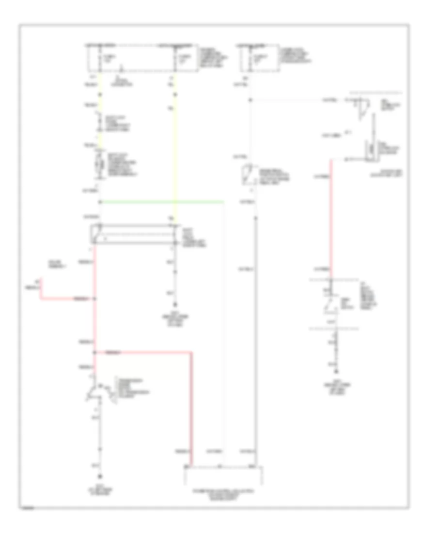
SHIFT INTERLOCK
Shift Interlock Wiring Diagram for Acura MDX Touring 2004
List of elements for Shift Interlock Wiring Diagram for Acura MDX Touring 2004:
- (not used)
- A/t shift switch (behind center console panel)
- B21
- B39
- Brake pedal position switch (at top of brake pedal arm)
- Driver's underdash fuse/relay box (behind left end of dash)
- Fuse 47 20a
- Fuse 8 7.5a
- Fuse 9 10a
- G101 (at left rear of engine)
- G401 (behind upper left end of dash)
- Gauge assembly
- Hot at all times
- Hot in acc or on
- Hot in on or start
- Ignition key switch/ key light
- Key interlock solenoid
- Key interlock switch
- M11
- Option connector
- Park pin switch
- Powertrain control mdule (pcm) (on right side of engine compt)
- Shift lock diode (under right side of dash)
- Shift lock relay (under left side of dash)
- Shift lock solenoid (under center console, at base of shift lever assembly)
- Transmission range switch (on transmission housing)
- Under-hood fuse/relay box (at right side of engine compt)
 English