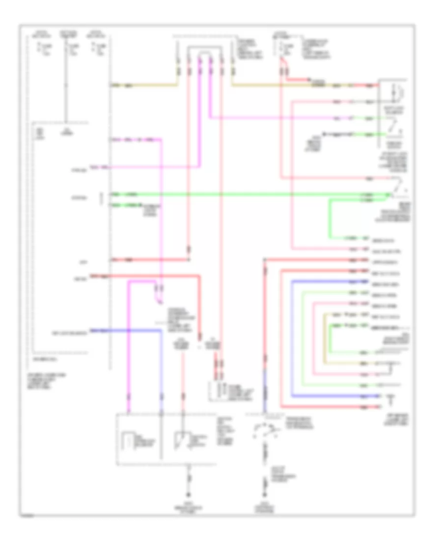
SHIFT INTERLOCK
Shift Interlock Wiring Diagram for Acura TL SH-AWD 2009
List of elements for Shift Interlock Wiring Diagram for Acura TL SH-AWD 2009:
- (atpp) drive in
- (bksw) sw in
- (sls) valve ctrl
- A/t shift lock solenoid/park pin switch (under center console)
- A16
- A18
- A19
- A24
- A25
- A26
- A27
- Acc key lock
- App sensor (under left side of dash)
- At-p
- Brake pedal position switch (on brake pedal mounting bracket)
- C14
- C25 pcu key
- Console accessory power socket relay (under left side of dash)
- Driver's junction box 1 (behind left side of dash)
- Driver's micu
- Driver's under-dash fuse/relay box (under left end of dash)
- E12
- Exterior lights system
- F20
- Fuse 20a
- Fuse 7.5a
- G101 (top front of engine)
- G403 (behind middle of dash)
- Horns system
- Hot at all times
- Hot in acc or on
- Hot in on or start
- Ig1 meter
- Ignition key switch
- Ignition key switch/ key light (w/o keyless access)
- J/c c107 (top of transmission housing)
- Key interlock solenoid
- Key lock solenoid
- Key sw
- P-pin sw
- P13
- P20
- Park pin switch
- Pcm (right side of engine compt)
- Pcu in
- Pnk
- Power control unit (under left side of dash)
- Q13
- Q14
- Q18
- Red
- Ref volt (vcc3)
- Ref volt (vcc4)
- Sens gnd (sg3)
- Sens gnd (sg4)
- Sens in (apsa)
- Sens in (apsb)
- Shift lock solenoid
- Stop sw
- Transmission range switch (on transaxle)
- Under-hood fuse/relay box (left rear of engine compt)
- W/ keyless access
- W/o keyless access
 English