SHIFT INTERLOCK
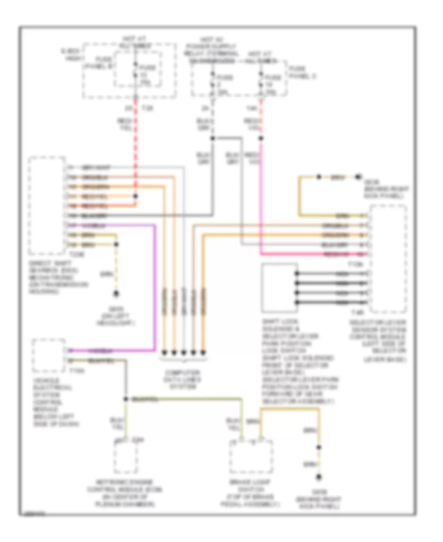
Shift Interlock Wiring Diagram for Audi A3 2008
List of elements for Shift Interlock Wiring Diagram for Audi A3 2008:
- 14a
- Brake light switch (top of brake pedal assembly)
- Computer data lines system
- Direct shift gearbox (dsg) mechatronic (on transmission housing)
- E-box high
- Fuse 10a
- Fuse 15a
- Fuse panel b
- Fuse panel c
- G638 (behind right kick panel)
- G655 (on left headlight)
- Hot at all times
- Lever base)
- Motronic engine control module (ecm) (in center of plenum chamber)
- Nca
- Selector lever sensor system control module (left side of selector
- Shift lock solenoid & selector lever park position lock switch (shift lock solenoid: front of selector lever base) (selector lever park position lock switch: forward of gear selector assembly)
- T10k
- T16a
- T20e
- T26
- T4r
- T94
- Vehicle electrical system control module (below left side of dash)
 English