
SHIFT INTERLOCK
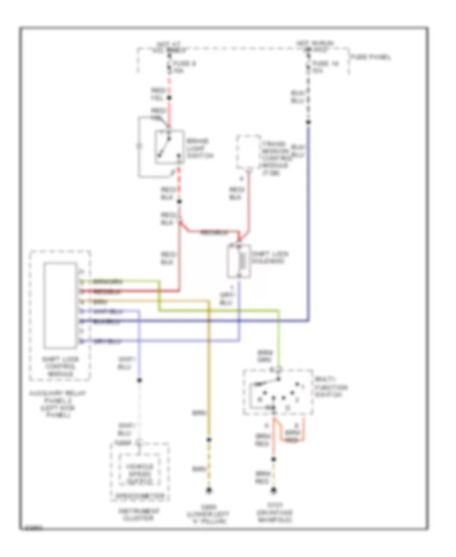
Shift Interlock Wiring Diagram for Audi A6 1995
List of elements for Shift Interlock Wiring Diagram for Audi A6 1995:
ANTI-THEFTAIR CONDITIONINGANTI-LOCK BRAKESCOOLING FANCOMPUTER DATA LINESCRUISE CONTROLELECTRONIC POWER STEERINGDEFOGGERSEXTERIOR LIGHTSENGINE PERFORMANCEGROUND DISTRIBUTIONINSTRUMENT CLUSTERHORNHEADLIGHTSINTERIOR LIGHTSPOWER TOP/SUNROOFMEMORY SYSTEMSPOWER DISTRIBUTIONSTARTING/CHARGINGPOWER SEATSPOWER WINDOWSSHIFT INTERLOCKPOWER DOOR LOCKSSUPPLEMENTAL RESTRAINTSRADIOTRANSMISSIONTRUNK, TAILGATE, FUEL DOORWARNING SYSTEMSWIPER/WASHER