SHIFT INTERLOCK
Electronic Parking Brake Wiring Diagram for Audi A6 3.2 2010

List of elements for Electronic Parking Brake Wiring Diagram for Audi A6 3.2 2010:
- (on right rear caliper assembly) right parking brake motor
- (right side of
- 23a
- Computer data lines system
- Electro-mechanical
- Fuse 30a
- Fuse 5a
- Fuse holder
- Fuse panel sb
- Fuse panel sf
- G51 (on right rear wheelwell)
- Hot at all times
- Instrument cluster control module
- Interior lights system
- Left parking brake motor (on left rear caliper assembly)
- Luggage compt)
- Parking brake
- Parking brake pressure switch
- Power distribution system
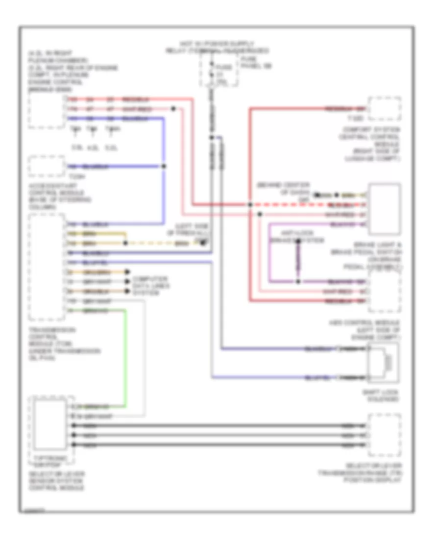
Shift Interlock Wiring Diagram, 6 Speed A/T for Audi A6 3.2 2010
List of elements for Shift Interlock Wiring Diagram, 6 Speed A/T for Audi A6 3.2 2010:
- (4.2l: in right plenum chamber) (5.2l: right rear of engine compt, in plenum) engine control module (ecm)
- (behind center of dash) g45
- (left side of firewall) g645
- 3.0l
- 31a
- 4.2l
- 5.2l
- Abs control module (left side of engine compt)
- Access/start control module (base of steering column)
- Anti-lock brakes system
- Brake light & brake pedal switch (on brake pedal assembly)
- Comfort system central control module (right side of luggage compt)
- Computer data lines system
- Fuse 15a
- Fuse panel sb
- Nca
- Selector lever sensor system control module
- Selector lever transmission range (tr) position display
- Shift lock solenoid
- T20h
- T32d
- T94
- T94a
- Tiptronic switch
- Transmission control module (tcm) (under transmission oil pan)
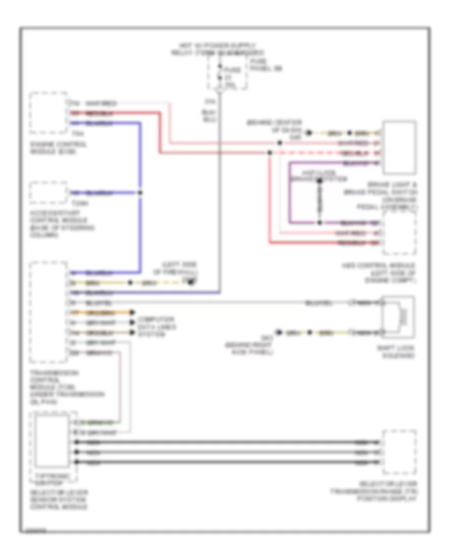
Shift Interlock Wiring Diagram, CVT for Audi A6 3.2 2010
List of elements for Shift Interlock Wiring Diagram, CVT for Audi A6 3.2 2010:
- (behind center of dash) g45
- (left side of firewall) g645
- 31a
- Abs control module (left side of engine compt)
- Access/start control module (base of steering column)
- Anti-lock brakes system
- Brake light & brake pedal switch (on brake pedal assembly)
- Computer data lines system
- Engine control module (ecm)
- Fuse 15a
- Fuse panel sb
- G43 (behind right kick panel)
- Nca
- Selector lever sensor system control module
- Selector lever transmission range (tr) position display
- Shift lock solenoid
- T20h
- T94
- Tiptronic switch
- Transmission control module (tcm) (under transmission oil pan)