SHIFT INTERLOCK
Shift Interlock Wiring Diagram, with CVT for Audi allroad Quattro 2005

List of elements for Shift Interlock Wiring Diagram, with CVT for Audi allroad Quattro 2005:
- 13a
- 31a
- Brake light switch (on brake pedal support)
- Fuse 10a
- Fuse 15a
- Fuse panel (left side of dash)
- G12 (left side
- G213 (lower right "a" pillar)
- Hot at all times
- Ignition switch
- Of engine compt)
- Off
- Run
- Shift lock solenoid (under center console)
- Start
- Tiptronic switch
- Transmission control module (tcm) (w/ 01j trans) (under right front seat)
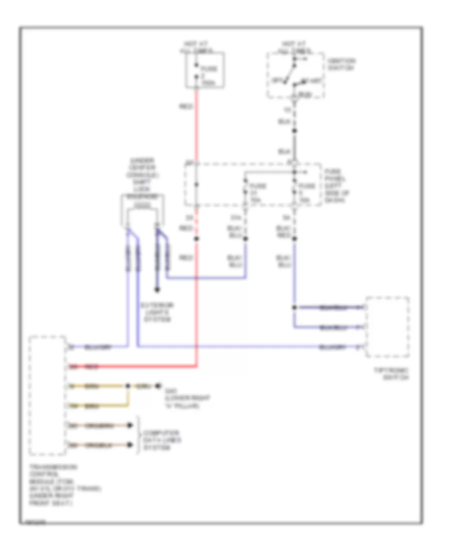
Shift Interlock Wiring Diagram, without CVT for Audi allroad Quattro 2005
List of elements for Shift Interlock Wiring Diagram, without CVT for Audi allroad Quattro 2005:
- "a" pillar)
- (under center console) shift lock solenoid
- 31a
- Computer data lines system
- Exterior lights system
- Fuse 10a
- Fuse 150a
- Fuse 15a
- Fuse panel (left side of dash)
- G43 (lower right
- Hot at all times
- Ignition switch
- Off
- Red
- Run
- Start
- Tiptronic switch
- Transmission control module (tcm) (w/ 01l or 01v trans) (under right front seat)