SHIFT INTERLOCK
Park Brake Release Wiring Diagram for Audi Q5 Premium Plus 2013

List of elements for Park Brake Release Wiring Diagram for Audi Q5 Premium Plus 2013:
- Abs control module (on abs hydraulic control unit)
- Auto- hold switch
- Clutch position sensor (m/t) (above clutch pedal assembly)
- Computer data lines system
- Electro- mechanical parking brake control module (right side of luggage compt)
- Electro-mechanical parking brake button
- Fuse 30a
- Fuse 5a
- Fuse carrier 1
- Fuse carrier 2
- Fuse carrier 3
- Fuse panel sc (lower left side of dash)
- Fuse panel sf (right side of luggage compt)
- G51 (right "d" pillar)
- Hot at all times
- Hot w/ power suply relay (terminal 15) energized
- Interior lights system
- Left parking brake motor
- Right parking brake motor
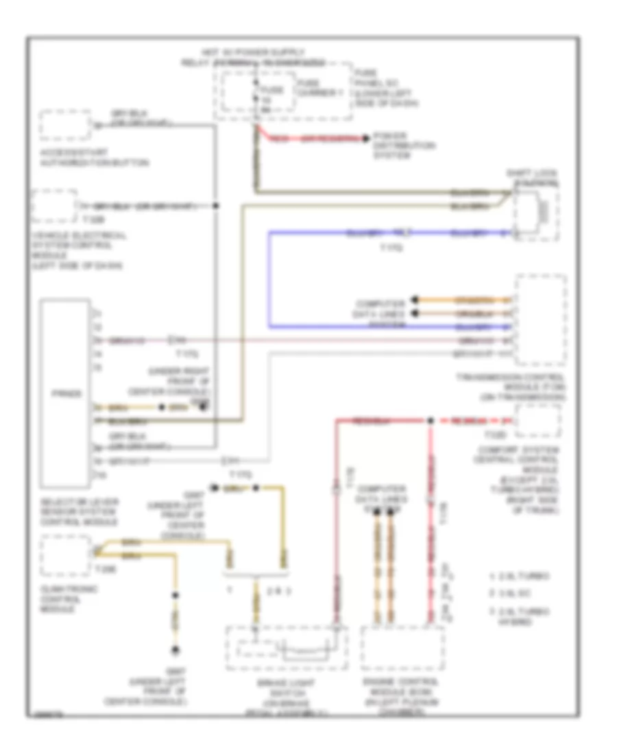
Shift Interlock Wiring Diagram for Audi Q5 Premium Plus 2013
List of elements for Shift Interlock Wiring Diagram for Audi Q5 Premium Plus 2013:
- (under right front of center console) g688
- 10a
- 2.0l turbo
- 2.0l turbo hybrid
- 3.0l sc
- Access/start authorization button
- Brake light switch (on brake pedal assembly)
- Climatronic control module
- Comfort system central control module (except 2.0l turbo hybrid) (right side of trunk)
- Computer data lines system
- Engine control module (ecm) (in left plenum chamber)
- Fuse 5a
- Fuse carrier 1
- Fuse panel sc (lower left side of dash)
- G687 (under left front of center console)
- Power distribution system
- Prnds
- Red
- Selector lever sensor system control module
- Shift lock solenoid
- T17e
- T17q
- T17r
- T20e
- T32b
- T32d
- T91
- T94
- Transmission control module (tcm) (on transmission)
- Vehicle electrical system control module (left side of dash)
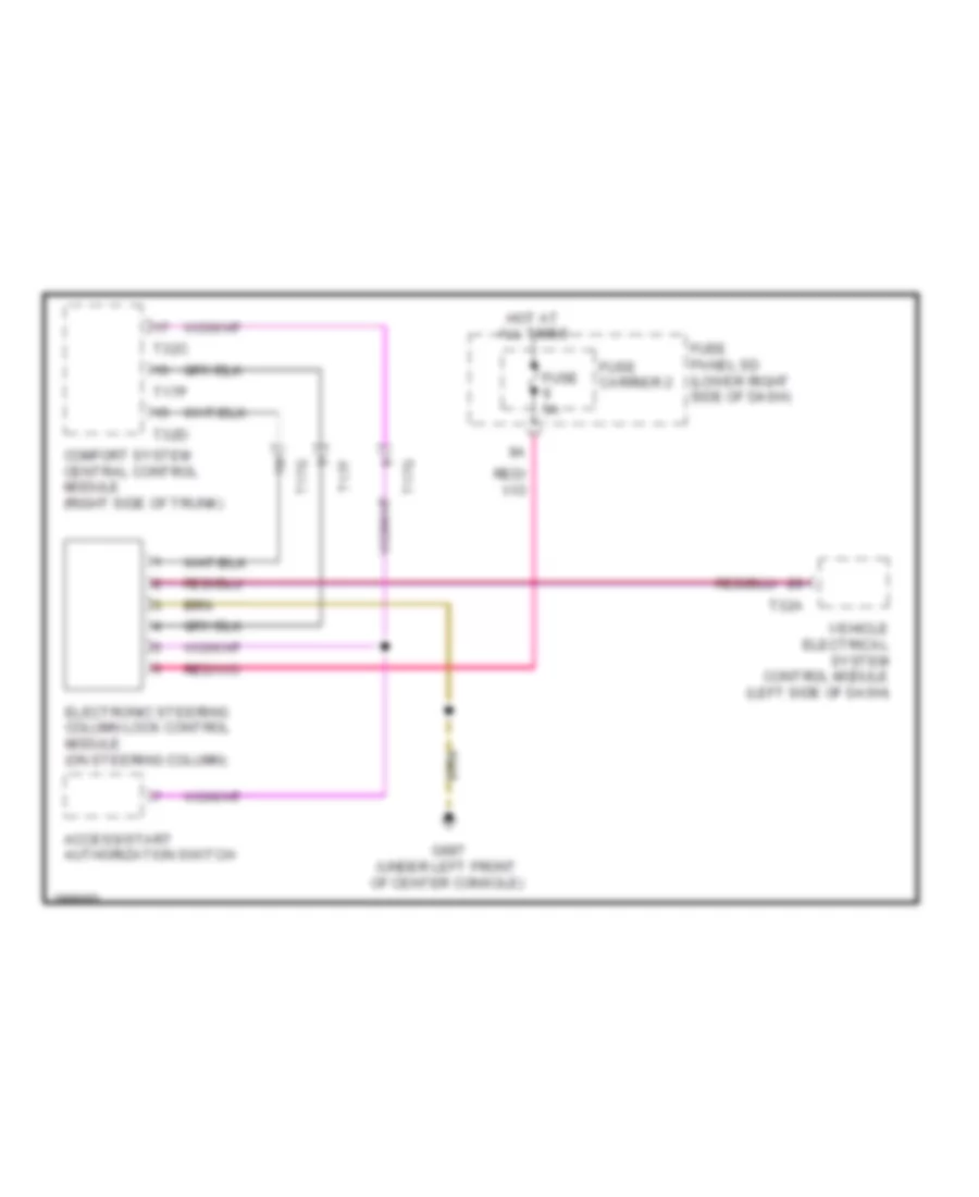
Steering Column Wiring Diagram for Audi Q5 Premium Plus 2013
List of elements for Steering Column Wiring Diagram for Audi Q5 Premium Plus 2013:
- Access/start authorization switch
- Comfort system central control module (right side of trunk)
- Electronic steering column lock control module (on steering column)
- Fuse 5a
- Fuse carrier 2
- Fuse panel sd (lower right side of dash)
- G687 (under left front of center console)
- Hot at all times
- T17f
- T17g
- T17p
- T32a
- T32c
- T32d
- Vehicle electrical system control module (left side of dash)