SHIFT INTERLOCK
Electronic Parking Brake Wiring Diagram for Audi S6 2014

List of elements for Electronic Parking Brake Wiring Diagram for Audi S6 2014:
- Abs control module (part of abs hydraulic unit)
- Auto hold button
- Computer data lines system
- Electro- mechanical parking brake control module (right side of luggage compt)
- Electro-mechanical parking brake button
- Fuse 30a
- Fuse 5a
- Fuse carrier
- G51 (right side of luggage compt)
- Hot at all times
- Interior lights system
- Left parking brake motor (on left rear caliper assembly)
- Relay & fuse panel b (left end of dash)
- Relay & fuse panel f (right rear of luggage compt)
- Right parking brake motor (on right rear caliper assembly)
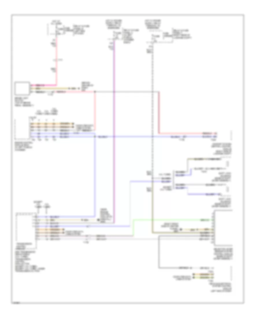
Shift Interlock Wiring Diagram for Audi S6 2014
List of elements for Shift Interlock Wiring Diagram for Audi S6 2014:
- (behind center of dash) g45
- (near engine control module on firewall) g645
- (right front side of center tunnel) g687
- 12a
- 2.0l turbo
- 3.0l sc
- 3.0l turbo diesel
- 4.0l turbo
- Brake light switch (top of brake pedal assembly)
- Comfort system central control module (right side of luggage compt)
- Computer data lines system
- Dsg transmission mechatronic (4.0l turbo) transmission control module (tcm) (except 4.0l turbo) (except 4.0l turbo: under transmission oil pan)
- Engine control module (ecm) (in left plenum chamber)
- Except 4.0l turbo
- Fuse 5a
- Fuse carrier
- Hot at all times
- Nca
- Relay & fuse panel a (in left plenum chamber e-box)
- Relay & fuse panel b (left end of dash)
- Relay & fuse panel f (right rear of luggage compt)
- Selector lever sensor system control module (base of shift lever assembly)
- Shift lock solenoid (base of shift lever assembly)
- T16c
- T17a
- T17b
- T17i
- T17o
- T32a
- T32g
- T4ca
- T91
- T94
- Transmission control module
- Vehicle electrical system control module (left end of dash)