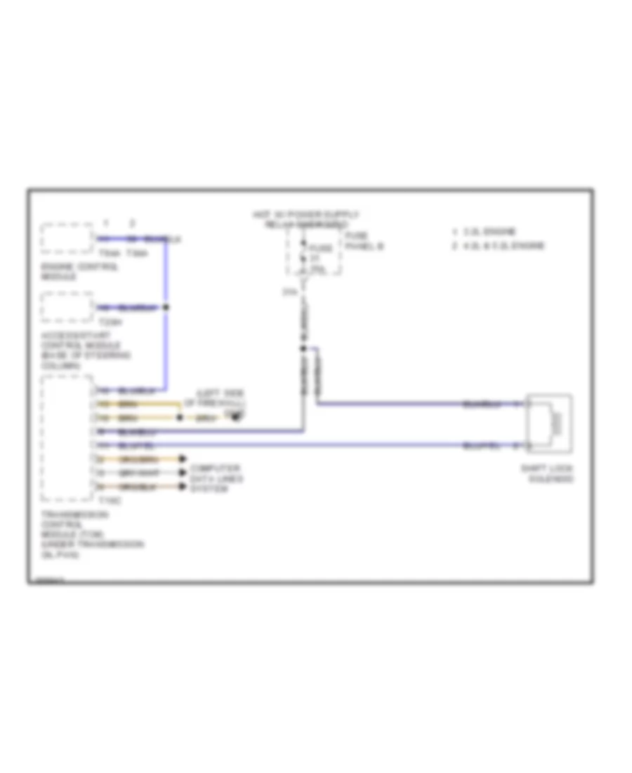
SHIFT INTERLOCK
Electronic Parking Brake Wiring Diagram for Audi S6 Quattro 2007

List of elements for Electronic Parking Brake Wiring Diagram for Audi S6 Quattro 2007:
- (on right rear caliper assembly) right parking brake motor
- 23a
- Computer data lines system
- Electronic parking brake control module (right rear of luggage compt)
- Fuse 30a
- Fuse 5a
- Fuse panel b
- Fuse panel f1
- G51 (on right rear wheelwell)
- Hot at all times
- Instrument cluster control module
- Interior lights system
- Left parking brake motor (on left rear caliper assembly)
- Parking brake pressure switch
- Power distribution system
- T30
- T32
Shift Interlock Wiring Diagram for Audi S6 Quattro 2007
List of elements for Shift Interlock Wiring Diagram for Audi S6 Quattro 2007:
- (left side of firewall) g645
- 3.2l engine
- 31a
- 4.2l & 5.2l engine
- Access/start control module (base of steering column)
- Computer data lines system
- Engine control module
- Fuse 15a
- Fuse panel b
- Shift lock solenoid
- T16c
- T20h
- T94a
- Transmission control module (tcm) (under transmission oil pan)