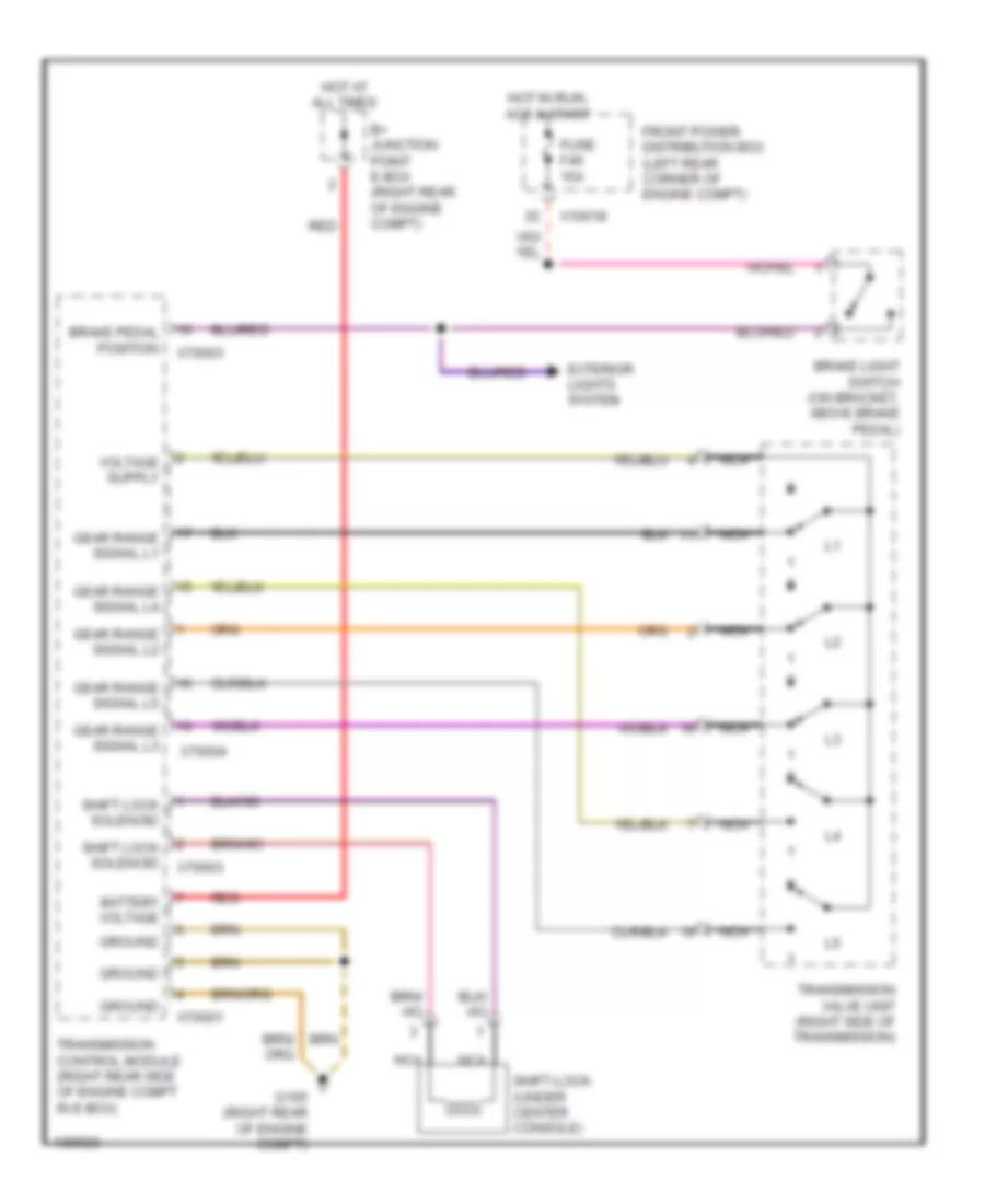
AUTOMOTIVE ELECTRICIANS PORTAL

SHIFT INTERLOCK – BMW M Coupe 2001 – SYSTEM WIRING DIAGRAMS

SHIFT INTERLOCK

Shift Interlock Wiring Diagram for BMW M Coupe 2001

Shift Interlock Wiring Diagram for BMW M Coupe 2001 https://portal-diagnostov.com/license.html
https://portal-diagnostov.com/license.html Automotive Electricians Portal FZCO Automotive Electricians Portal FZCO
Získejte přístup ke všem schématům zapojení automobiluDownload PDF file

List of elements for Shift Interlock Wiring Diagram for BMW M Coupe 2001:

  • B+ junction point e-box (right rear of engine compt)
  • Battery voltage
  • Brake light switch (on bracket, above brake pedal)
  • Brake pedal position
  • Exterior lights system
  • Front power distribution box (left rear corner of engine compt)
  • Fuse f46 15a
  • G105 (right rear of engine compt)
  • Gear range signal l1
  • Gear range signal l2
  • Gear range signal l3
  • Gear range signal l4
  • Gear range signal l5
  • Ground
  • Hot at all times
  • Hot in run, acc & start
  • Nca
  • Red
  • Shift lock solenoid
  • Shift-lock (under center console)
  • Transmission control module (right rear side of engine compt in e-box)
  • Transmission valve unit (right side of transmission)
  • X10018
  • X70001
  • X70003
  • X70004