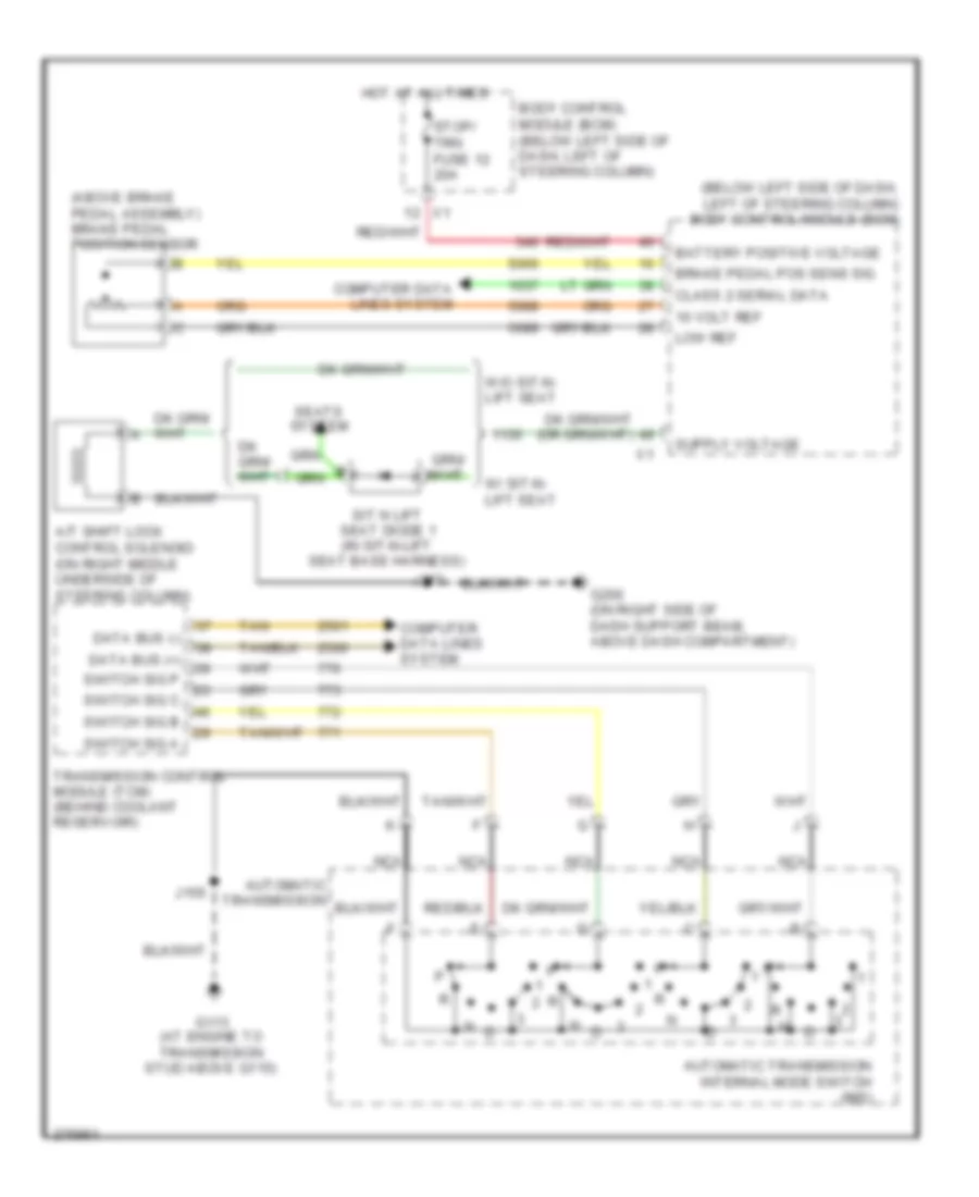
SHIFT INTERLOCK
Shift Interlock Wiring Diagram for Chevrolet Uplander LS 2008
List of elements for Shift Interlock Wiring Diagram for Chevrolet Uplander LS 2008:
- (above brake pedal assembly) brake pedal position sensor
- (below left side of dash, left of steering column) body control module (bcm)
- 10 volt ref
- A/t shift lock control solenoid (on right middle underside of steering column)
- Automatic transmission
- Automatic transmission internal mode switch (ims)
- Battery positive voltage
- Body control module (bcm) (below left side of dash, left of steering column)
- Brake pedal pos sens sig
- Class 2 serial data
- Computer data lines system
- Data bus (+)
- Data bus (-)
- G113 (at engine to transmission stud above g115)
- G200 (on right side of dash support beam, above dash compartment)
- Hot at all times
- J155
- J277
- Low ref
- Nca
- Seats system
- Sit n lift seat diode 1 (in sit-n-lift seat base harness)
- Stop/ trn fuse 12 20a
- Switch sig a
- Switch sig b
- Switch sig c
- Switch sig p
- Tan
- Transmission control module (tcm) (behind coolant reservoir)
- W/ sit-n- lift seat
- W/o sit-n- lift seat
 English