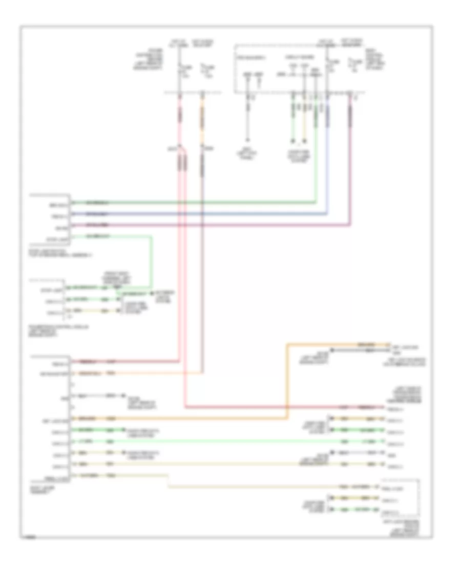
SHIFT INTERLOCK
Shift Interlock Wiring Diagram for Fiat 500 Abarth 2013
List of elements for Shift Interlock Wiring Diagram for Fiat 500 Abarth 2013:
- (front body harness, left side of dash) s009
- (left side of transmission) transmission control module
- A107
- Anti-lock brakes module (left rear of engine compt)
- B134
- Body control module (left end of dash)
- Brk sig 2
- Can c (+)
- Can c (-)
- Circuit board
- Computer data lines system
- D64
- D65
- Exterior lights system
- F202
- Fsd b (+)
- Fuse 10a
- Fuse 5a
- Fuse 7.5a
- G010b (left rear of engine compt)
- G021 (left kick panel)
- Gnd
- Hot at all times
- Hot in run or start
- Ign rs
- Ign run/start
- K320
- Key lock sig
- Key lock solenoid (on steering column)
- L56
- Pdc bus bar 3
- Pndl hi sw
- Power distribution center (left rear of engine compt)
- Powertrain control module (left rear of engine compt)
- Prndl hi sw
- S019
- S056
- Shift lever assembly
- Stop lamp
- Stop lamp switch (top of brake pedal assembly)
- T824
- Z910
 English