SHIFT INTERLOCK
Shift Interlock Wiring Diagram, with Stripped Chassis for Ford Cutaway E250 2012

List of elements for Shift Interlock Wiring Diagram, with Stripped Chassis for Ford Cutaway E250 2012:
- Battery junction box (bjb) (left front of engine compt)
- Brake pedal position switch
- Brake shift interlock (steering column)
- C275
- Detect sw
- Fuse 10a
- G207 (center of dash)
- Hot at all times
- Instrument panel cluster (ipc)
- Park
- S245 (main wiring harness, near breakout to g207)
- S260
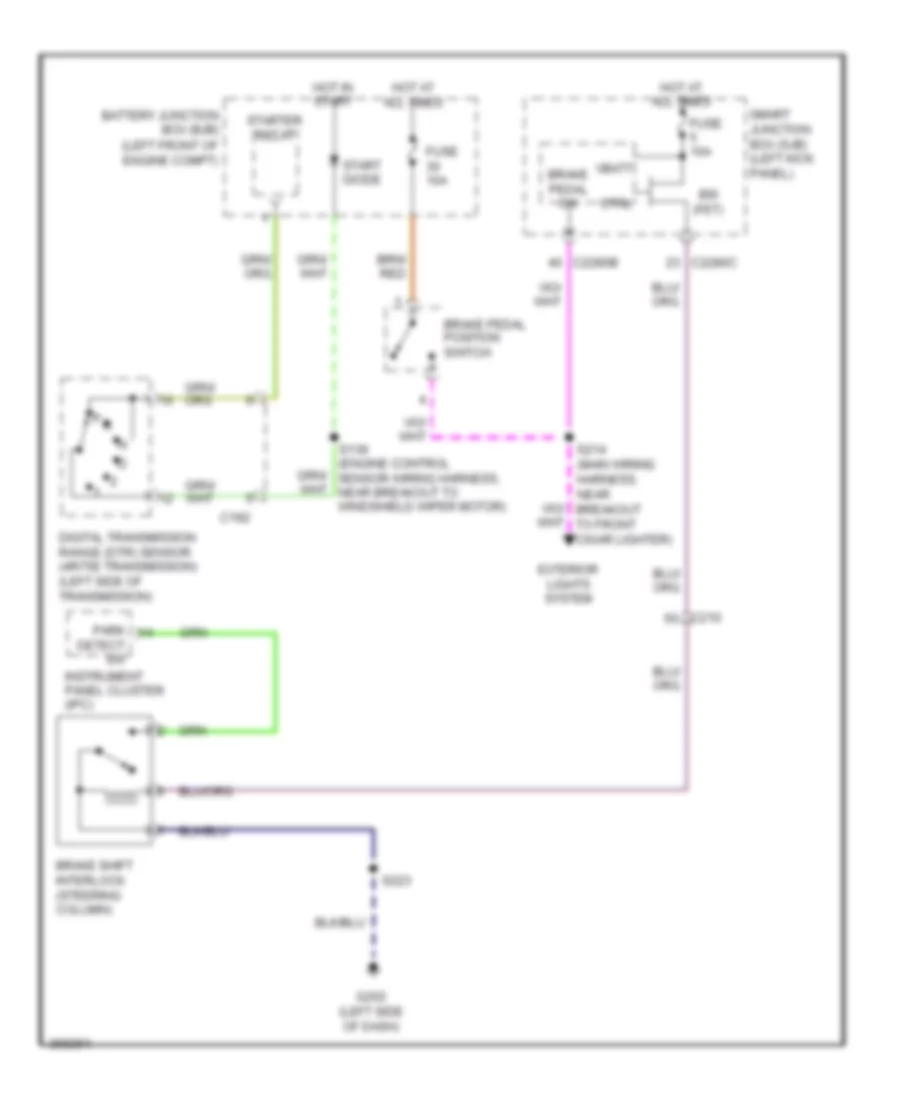
Shift Interlock Wiring Diagram, without Stripped Chassis for Ford Cutaway E250 2012
List of elements for Shift Interlock Wiring Diagram, without Stripped Chassis for Ford Cutaway E250 2012:
- (left front of engine compt)
- Battery junction box (bjb)
- Brake pedal position switch
- Brake pedal sw
- Brake shift interlock (steering column)
- Bsi (fet)
- C192
- C210
- C2280b
- C2280c
- Ctrl
- Detect sw
- Digital transmission range (dtr) sensor (4r75e transmission) (left side of transmission)
- Exterior lights system
- Fuse 10a
- G202 (left side of dash)
- Hot at all times
- Hot in start
- Instrument panel cluster (ipc)
- P r
- Park
- S214 (main wiring harness, near breakout to front cigar lighter)
- S223
- Smart junction box (sjb) (left kick panel)
- Start diode
- Starter relay
- Vbatt