SHIFT INTERLOCK
Shift Interlock Wiring Diagram, with Stripped Chassis for Ford E450 Super Duty 2010

List of elements for Shift Interlock Wiring Diagram, with Stripped Chassis for Ford E450 Super Duty 2010:
- Battery junction box (bjb) (left front of engine compt)
- Brake shift interlock (steering column)
- Detect sw
- Fuse 10a
- G207 (center of dash)
- Hot at all times
- Instrument panel cluster (ipc)
- Park
- S245 (main wiring harness, near breakout to g207)
- S260
- Stoplamp switch (under left side of dash)
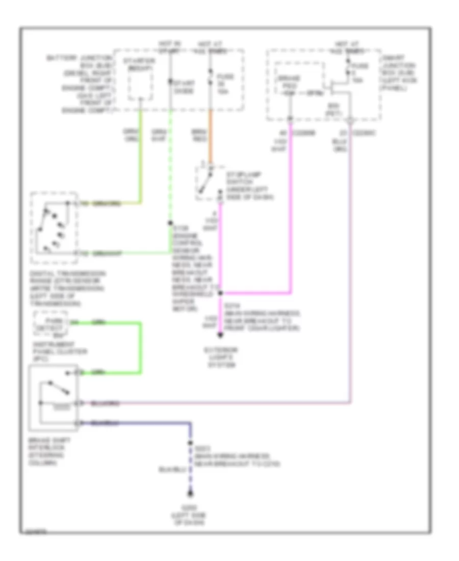
Shift Interlock Wiring Diagram, without Stripped Chassis for Ford E450 Super Duty 2010
List of elements for Shift Interlock Wiring Diagram, without Stripped Chassis for Ford E450 Super Duty 2010:
- Battery junction box (bjb) (diesel: right front of engine compt) (gas: left front of engine compt)
- Brake ped sw
- Brake shift interlock (steering column)
- Bsi (fet)
- C2280b
- C2280c
- Ctrl
- Detect sw
- Digital transmission range (dtr) sensor (4r75e transmission) (left side of transmission)
- Exterior lights system
- Fuse 10a
- G202 (left side of dash)
- Hot at all times
- Hot in start
- Instrument panel cluster (ipc)
- P r
- Park
- S139 (engine control sensor wiring har- ness, near breakout ness, near breakout to windshield wiper motor)
- S214 (main wiring harness, near breakout to front cigar lighter)
- S223 (main wiring harness, near breakout to c210)
- Smart junction box (sjb) (left kick panel)
- Start diode
- Starter relay
- Stoplamp switch (under left side of dash)