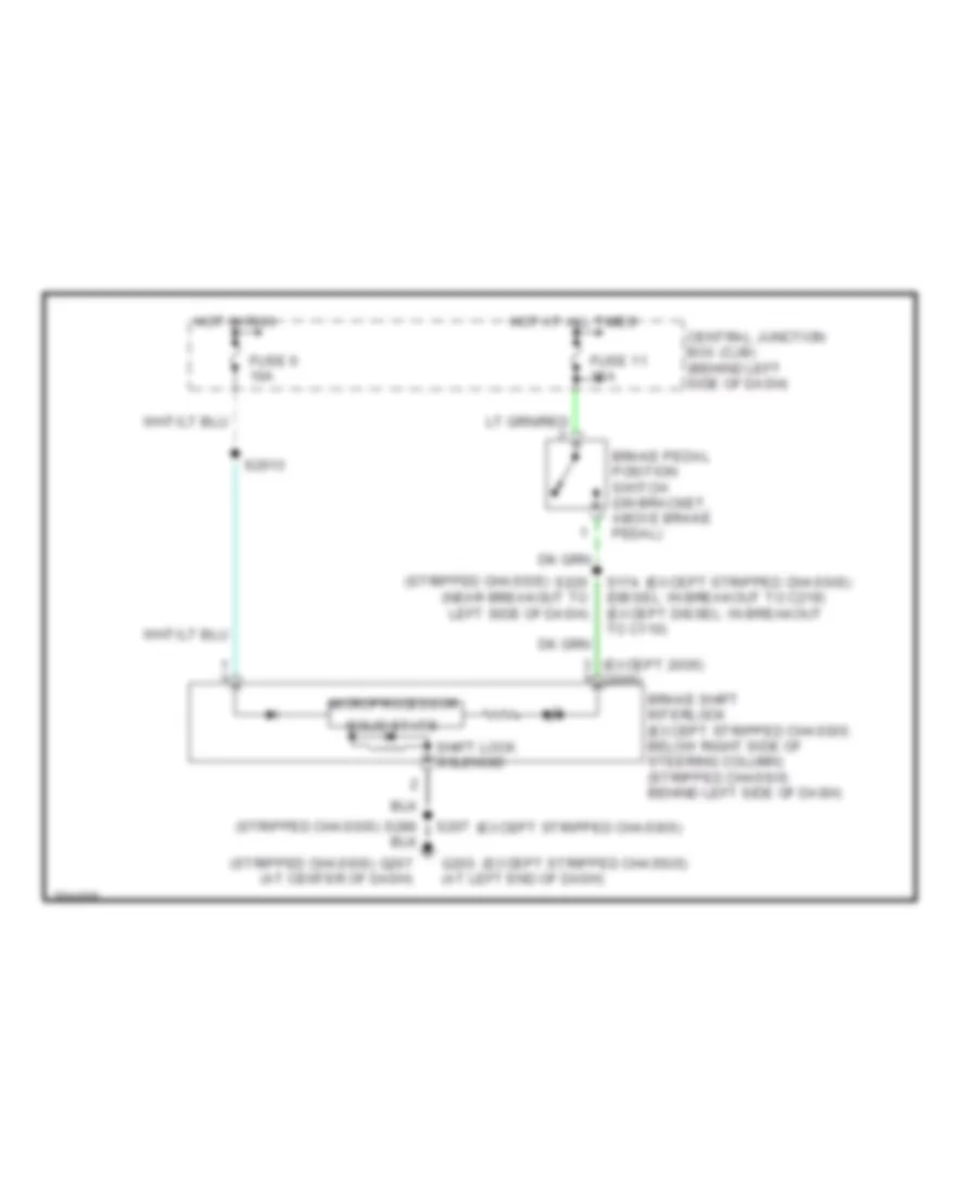
AUTOMOTIVE ELECTRICIANS PORTAL

SHIFT INTERLOCK – Ford Econoline E150 2005 – SYSTEM WIRING DIAGRAMS

SHIFT INTERLOCK

Shift Interlock Wiring Diagram for Ford Econoline E150 2005

Shift Interlock Wiring Diagram for Ford Econoline E150 2005 https://portal-diagnostov.com/license.html
https://portal-diagnostov.com/license.html Automotive Electricians Portal FZCO Automotive Electricians Portal FZCO
Získejte přístup ke všem schématům zapojení automobiluDownload PDF file

List of elements for Shift Interlock Wiring Diagram for Ford Econoline E150 2005:

  • (except 2005) (2005)
  • (except stripped chassis)
  • (stripped chassis)
  • Brake pedal position switch (on bracket, above brake pedal)
  • Brake shift interlock (except stripped chassis: below right side of steering column) (stripped chassis: behind left side of dash)
  • Central junction box (cjb) (behind left side of dash)
  • Fuse 11 15a
  • Fuse 6 10a
  • G203 (at left end of dash)
  • G207 (at center of dash)
  • Hot at all times
  • Hot in run
  • Microprocessor
  • S174 (diesel: in breakout to c219) (except diesel: in breakout to c110)
  • S2013
  • S207
  • S220 (near breakout to left side of dash)
  • Shift lock solenoid
  • Solid state