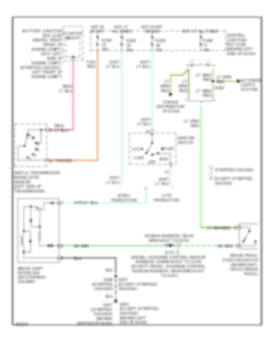
SHIFT INTERLOCK
Shift Interlock Wiring Diagram for Ford Econoline E250 2008
List of elements for Shift Interlock Wiring Diagram for Ford Econoline E250 2008:
- (in main harness, near breakout to c219) s220
- Acc
- Battery junction box (cjb) (diesel: right front of engine compt) (gas: left side of engine compt) (stripped chassis : left front of engine compt)
- Brake pedal position switch (on bracket, above brake pedal)
- Brake shift interlock (on steering column)
- Central junction box (cjb) (behind left side of dash)
- Digital transmission range (dtr) sensor (left side of transmission)
- Early production
- Except stripped chassis
- Exterior lights system
- Fuse 10a
- Fuse 15a
- G203 (except stripped chassis) (behind left end of dash)
- G207 (stripped chassis) (behind center of dash)
- Hot at all times
- Hot in off or run
- Hot in start
- Ignition switch
- Late production
- Lock
- Off
- P r
- Power distribution system
- Run
- S174 (diesel: in engine control sensor harness, in breakout to c219) (except diesel: in engine control sensor harness, near breakout to g101)
- S207 (except stripped chassis)
- S282
- S286 (stripped chassis)
- Start
- Starter relay
- Stripped chassis
- Tan/ red
- Tan/red
 English