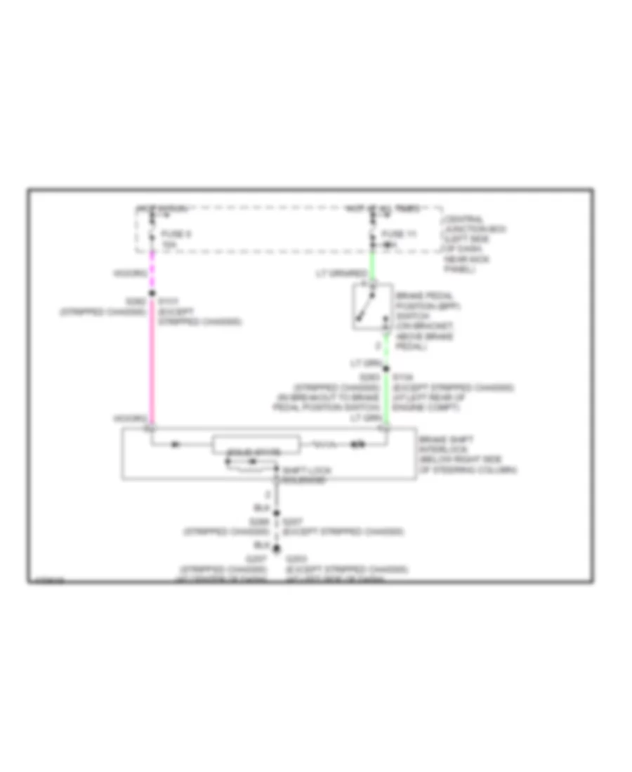
AUTOMOTIVE ELECTRICIANS PORTAL

SHIFT INTERLOCK – Ford Econoline E350 Super Duty 2003 – SYSTEM WIRING DIAGRAMS

SHIFT INTERLOCK

Shift Interlock Wiring Diagram for Ford Econoline E350 Super Duty 2003

Shift Interlock Wiring Diagram for Ford Econoline E350 Super Duty 2003 https://portal-diagnostov.com/license.html
https://portal-diagnostov.com/license.html Automotive Electricians Portal FZCO Automotive Electricians Portal FZCO
Tüm kablolama şemalarına erişin arabaDownload PDF file

List of elements for Shift Interlock Wiring Diagram for Ford Econoline E350 Super Duty 2003:

  • Brake pedal position (bpp) switch (on bracket, above brake pedal)
  • Brake shift interlock (below right side of steering column)
  • Central junction box (left side of dash, near kick panel)
  • Fuse 11 15a
  • Fuse 6 10a
  • G203 (except stripped chassis) (at left side of dash)
  • G207 (stripped chassis) (at center of dash)
  • Hot at all times
  • Hot in run
  • S131 (except stripped chassis)
  • S134 (except stripped chassis) (at left rear of engine compt)
  • S207 (except stripped chassis)
  • S282 (stripped chassis)
  • S286 (stripped chassis)
  • Shift lock solenoid
  • Solid state