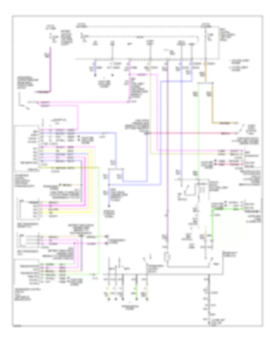
SHIFT INTERLOCK
Shift Interlock Wiring Diagram for Ford Edge SE 2012
List of elements for Shift Interlock Wiring Diagram for Ford Edge SE 2012:
- (battery cable wiring harness, near breakout to 6f35 transmission) s183
- (brake pedal support bracket) brake pedal position (bpp) switch
- (lower left "a"pillar) g200
- (main wiring harness, near breakout to passive anti-theft restraint module) s238
- (not used)
- 2.0l
- 6f35 transmission (2.0l)
- 6f50 transmission (except 2.0l)
- Access
- Battery junction box (bjb) (left side of engine compt)
- Body control module (bcm) (left kick panel)
- Bpp
- Brake shift
- Bsi (fet)
- C110
- C1381b
- C1520a
- C175b
- C175t
- C213
- C215
- C2153c
- C2153e
- C2280a
- C2280b
- C2280f
- C3053
- Ccb08
- Cdc35
- Cet40
- Computer data lines system
- Control
- Cpk34
- Except 2.0l
- Fuse 10a
- Fuse 15a
- Hot at all times
- Hs can +
- Hs can -
- Hs can+
- Hs can-
- Ignition switch (w/o intelligent access)
- Instrument panel cluster (ipc)
- Intelligent access) (main wiring harness, near breakout to g205)
- Interlock
- Key in ignition
- Le111
- Lock
- Micro
- Ms can+
- Ms can-
- Nca
- Park
- Park detect
- Powertrain control module (pcm) (right side of engine compt)
- Remote function actuator (rfa) module (w/ intelligent access) (behind glove box)
- Ret24
- S111 (dash panel to headlight junction wiring harness, near breakout to c134)
- S184 (battery cable wiring harness, near breakout to transmission control module)
- S200
- S285 (main wiring harness, near breakout to g205)
- Sstd
- Sstu
- Start
- Start/ stop 1
- Start/ stop 1 (active high)
- Start/stop
- Start/stop switch (w/ intelligent access) (center of dash)
- Starting/ charging system
- Switch
- Tr 1
- Tr 2
- Tr 3
- Tr 4
- Tr gnd
- Tr-p
- Transmission
- Transmission control module (2.0l) (left side of engine compt)
- Transmission system
- Transmissions system
- Trs
- Trsw-pin
- Trsw-pn
- Tss/oss/tr gnd
- Tss/oss/trvpwr
- Vdb04
- Vdb05
- Vdb06
- Vdb07
- Vet29
- Vet30
- Vet31
- Vet32
- W/ intelligent
- W/o intelligent
 English