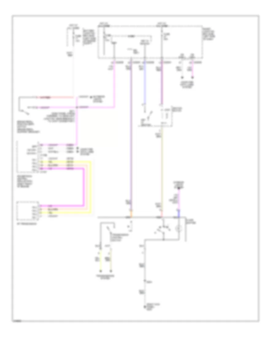
SHIFT INTERLOCK
Shift Interlock Wiring Diagram for Ford Edge SEL 2010
List of elements for Shift Interlock Wiring Diagram for Ford Edge SEL 2010:
- (right kick panel) g202
- 6f transmission
- Battery junction box (bjb) (left side of engine compt)
- Bpp
- Brake pedal position (bpp) switch (brake pedal support bracket)
- Bsi (fet)
- C175b
- C175t
- C2280a
- C2280b
- C2280c
- Ccb08
- Computer data lines system
- Control
- Exterior lights system
- Floor
- Fuse 10a
- Fuse 20a
- Hot at all times
- Hs can +
- Hs can -
- Ignition switch
- Interior lights system
- Key in ignition
- Lock
- Micro
- Ms can +
- Ms can -
- N d
- Powertrain control module (pcm) (right front of engine)
- Red
- S204
- S211 (dash panel wiring harness, to headlight junction, near breakout to joint connector 7)
- Shifter
- Smart junction box (sjb) (left side of dash)
- Switch
- Tr 1
- Tr 2
- Tr 3
- Tr 4
- Transmission
- Transmissions system
- Vdb04
- Vdb05
- Vet29
- Vet30
- Vet31
- Vet32
 English