
SHIFT INTERLOCK
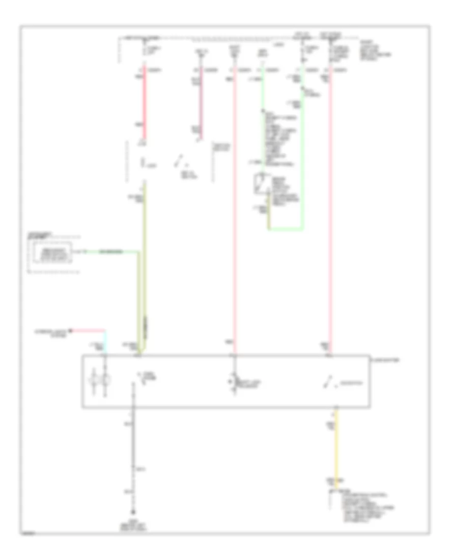
Shift Interlock Wiring Diagram for Ford Escape Hybrid 2007
List of elements for Shift Interlock Wiring Diagram for Ford Escape Hybrid 2007:
ANTI-THEFTBODY CONTROL MODULESANTI-LOCK BRAKESAIR CONDITIONINGCOMPUTER DATA LINESCOOLING FANELECTRONIC POWER STEERINGCRUISE CONTROLEXTERIOR LIGHTSGROUND DISTRIBUTIONDEFOGGERSENGINE PERFORMANCEINTERIOR LIGHTSINSTRUMENT CLUSTERNAVIGATIONHORNPOWER TOP/SUNROOFPOWER WINDOWSPOWER MIRRORSPOWER SEATSPOWER DOOR LOCKSPOWER DISTRIBUTIONHEADLIGHTSSHIFT INTERLOCKSTARTING/CHARGINGWARNING SYSTEMSTRANSMISSIONSUPPLEMENTAL RESTRAINTSRADIOWIPER/WASHER