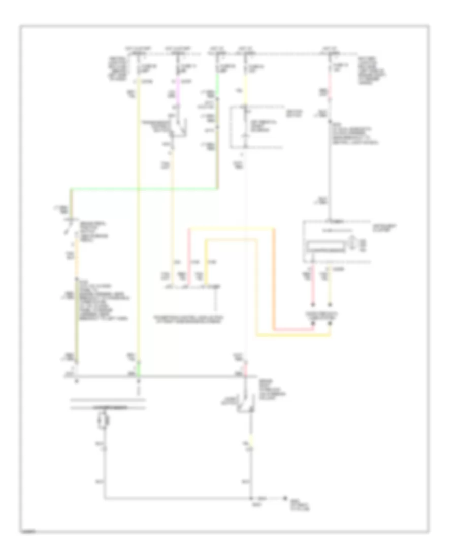
SHIFT INTERLOCK
Shift Interlock Wiring Diagram for Ford Explorer 2005
List of elements for Shift Interlock Wiring Diagram for Ford Explorer 2005:
- (on steering column)
- All times
- Battery junction box (bjb) (left side of engine compt, at fender apron)
- Brake pedal position switch (above brake pedal)
- Brake shift interlock
- C175b
- C220a
- C220b
- C270e
- C270f
- Central junction box (cjb) (behind left side of dash)
- Computer data lines system
- Fuse 13 5a
- Fuse 15 15a
- Fuse 23 30a
- Fuse 25 15a
- Fuse 26 7.5a
- G200 (at right "a" pillar)
- Hot at
- Hot in start
- Ignition switch
- Instrument cluster
- Key removal inhibit solenoid
- Micro switch
- Microprocessor
- Nca
- O/d off ind
- Or run
- Powertrain control module (pcm) (at right side engine bulkhead)
- Red
- S120 (w/o ivd: in dash panel to engine harness, near breakout to windshield wiper motor) (w/ ivd: in dash panel to engine harness, near breakout to left horn)
- S171 (w/o ivd)
- S173
- S223
- S232 (w/ dual zone eatc) (in main harness, near breakout to central junction box)
- Transmission control switch
 Русский