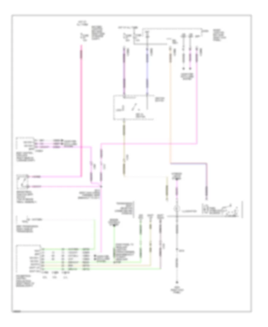
SHIFT INTERLOCK
Shift Interlock Wiring Diagram for Ford Mustang 2013
List of elements for Shift Interlock Wiring Diagram for Ford Mustang 2013:
- (dash panel to headlamp junction wiring harness, near breakout to right headlamp) s199
- (right kick panel)
- 3.7l
- 5.0l
- 5.8l
- 6r80 transmission (right side of transmission)
- All times
- Battery junction box (bjb) (right side of engine compt)
- Body control module b (right rear of luggage compt)
- Bpp
- Bpp c4368a
- Brake pedal position (bpp) switch (top of brake pedal assembly)
- Bsi (fet)
- C1381b
- C175b
- C210
- C211
- C219
- C2280a
- C2280b
- C2280c
- C265
- Ccb08
- Cet35
- Cet42
- Cet60
- Computer data lines system
- Engine controls system
- Fuse 10a
- Fuse 20a
- G203
- Hot at
- Hot at all times
- Hs can +
- Hs can -
- Ignition switch
- Illumination
- Interior lights system
- Key in ign
- Key in ignition
- Lock
- Micro
- Ms can +
- Ms can -
- Ms can+
- Ms can-
- Park interlock solenoid
- Powertrain control module (pcm) (right front of engine compt)
- Re405
- S213 (body main wiring harness, near breakout to c211)
- S319
- Shift dn
- Shift down
- Shift up
- Sig rtn
- Smart junction box (sjb) (right kick panel)
- Tr-p
- Transmission shift selector (under center console)
- Vdb04
- Vdb05
- Vdb06
- Vdb07
 English