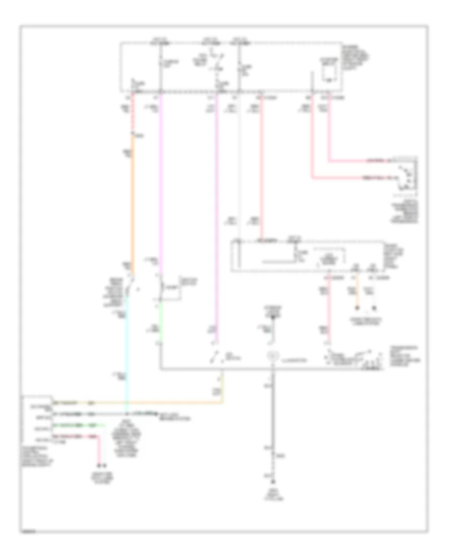
SHIFT INTERLOCK
Shift Interlock Wiring Diagram for Ford Mustang Shelby GT500KR 2009
List of elements for Shift Interlock Wiring Diagram for Ford Mustang Shelby GT500KR 2009:
- (right ``a" pillar)
- A9 c1035a
- Anti-lock brakes system
- Bpp sw
- Brake pedal position switch (on brake pedal support)
- Bussed electrical center (bec) (right front of engine
- C1035b e10
- C11
- C2280b
- C2280d
- C2280h
- Compt)
- Computer data lines system
- Digital transmission range (dtr) sensor (left side of transmission)
- Fuse 10a
- Fuse 15a
- Fuse 30a
- Fuse 68 20a
- G203
- Hot at all times
- Hot in start
- Hs can +
- Hs can - c175b
- Ignition switch
- Illumination
- Inhibit
- Interior lights system
- Low current board
- Ms can +
- Ms can -
- O/d switch
- Od cancel sw
- Park interlock solenoid
- Pcm power relay
- Powertrain control module (pcm) (right front of engine compt)
- S222
- S225
- S227 (w/ abs) (in body main harness, near breakout to left front channel subwoofer amplifier)
- Smart junction box (sjb) (right kick panel)
- Starter relay
- Transmission shift selector (under center console)
 English