SHIFT INTERLOCK
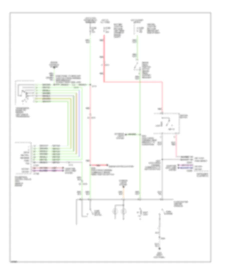
Shift Interlock Wiring Diagram for Ford Transit Connect 2012
List of elements for Shift Interlock Wiring Diagram for Ford Transit Connect 2012:
- 15s-ta21
- 15s-ta37
- 15s-ta38
- 15s-ta39
- 15s-ta40
- 15s-ta41
- 15s-ta42
- 4-ec7
- 5-ec7
- Battery junction box (bjb) (left rear corner of engine compt)
- Brake pedal position switch (brake pedal support bracket)
- C110
- C175b
- C175t
- C213
- C215
- C220a
- C220b
- Central junction box (cjb) (behind left side of dash)
- Computer data lines system
- Drive
- Engine controls system
- Exterior lights system
- Floor shifter (center console)
- Fuse 10a
- Fuse 15a
- Fuse 20a
- G203 (right kick panel)
- Hot at all times
- Hot in start or run
- Hot w/ pcm power relay energized
- Hs can+
- Hs can-
- Ignition switch
- Instrument cluster (ic)
- Interior lights system
- Key in
- Key in sw
- Lock
- Ms can+
- Ms can-
- Neutral
- Over drive switch
- Park
- Park detect
- Park range
- Powertrain control module (pcm) (rear of engine)
- Red
- Reverse
- S112
- S220
- S234 (main wiring harness, near breakout to microphone)
- S236 (main wiring harness, in breakout brake pedal position switch)
- S237 (main wiring harness, in breakout to ignition switch)
- Shift lock
- Tcs
- Transmission range (tr) sensor (left side of transmission)
 Русский