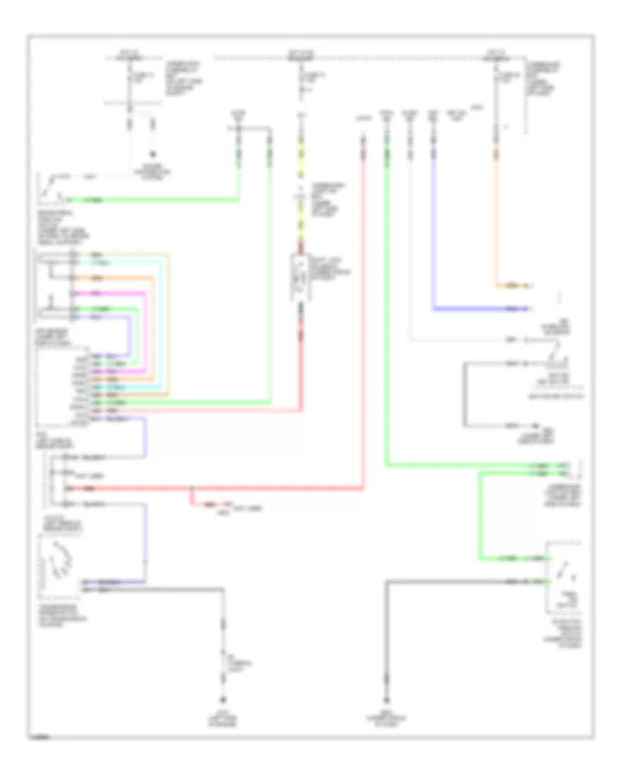
SHIFT INTERLOCK
Shift Interlock Wiring Diagram for Honda CR-V EX 2011
List of elements for Shift Interlock Wiring Diagram for Honda CR-V EX 2011:
- (not used)
- (not used) c502
- (thermal
- A16
- A18
- A19
- A25
- A26
- A28
- A35
- A36
- A42
- App sensor (under left side of dash)
- Apsa
- Apsb
- Atp-p
- B14
- Bksw
- Brake pedal position switch (under left side of dash, on brake pedal support)
- C13
- D3 switch/ park-pin switch (under middle of dash)
- F25
- F27
- F30
- Fuse 10 7.5a
- Fuse 12 15a
- Fuse 35 7.5a
- G101 (left side of engine)
- G501 (under left side of dash)
- G503 (under middle of dash)
- Hot at all times
- Hot in acc or on
- Hot in on or start
- Ig 1
- Ig key sw
- Ignition key switch
- J/c c101 (left rear of engine compt)
- J18
- Joint)
- Key interlock solenoid
- Key sol
- Key sw acc
- Micu
- P-pin sw
- Park- pin switch
- Pcm (left side of engine compt)
- Power distribution system
- R16
- Red
- Sg4
- Sg5
- Shift lock solenoid (under middle of dash)
- Sls
- Stop sw
- Transmission range switch (on transmission housing)
- Under-dash fuse/relay box (under left side of dash)
- Under-dash junction box (under left side of dash)
- Under-hood fuse/relay box (on left side of engine compt)
- Vcc4
- Vcc5
 English