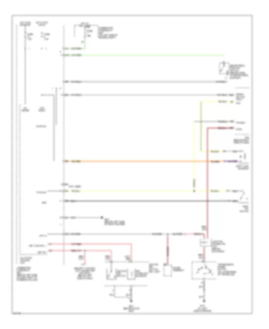
SHIFT INTERLOCK
Shift Interlock Wiring Diagram for Honda CR-V SE 2005
List of elements for Shift Interlock Wiring Diagram for Honda CR-V SE 2005:
- (bksw) switch input
- (not used)
- Acc radio
- Atp -n
- Atpn
- Brake pedal position switch (behind dash, on brake pedal support)
- C20
- E22
- Fuse 15a
- Fuse 7.5a
- G10
- G101 (at left side of engine)
- G301 (behind left side of front bumper)
- G401 (behind glove box)
- Gauge assembly
- Gnd
- Hot at all times
- Hot in acc or on
- Hot in on or start
- Ig1 meter
- Ignition key switch
- Ignition key switch/ key light
- Junction connector c105 (behind glove box)
- Key interlock solenoid
- Key lock sol +
- Key sw
- Multiplex control unit
- O12
- P pin sw
- P-pinsw
- Park pin switch
- Pcm (behind right side of dash)
- Security control unit connector (optional) (behind left side of dash)
- Shift lock solenoid
- Sls
- Stop sw
- Transmission range switch (on lower rear of transaxle)
- Under-dash fuse/relay box (behind left side of dash, right of steering column)
- Under-hood fuse/relay box (on left side of engine compt)
 Русский