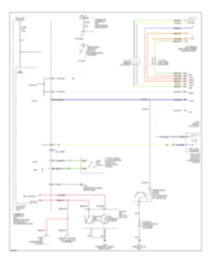
SHIFT INTERLOCK
Shift Interlock Wiring Diagram for Honda Element EX 2009
List of elements for Shift Interlock Wiring Diagram for Honda Element EX 2009:
- (not used)
- (under middle
- A/t shift lever illumination/park pin switch
- A20
- A21
- A23
- A24
- A25
- A26
- App sensor (right rear corner of engine compt)
- Apsa
- Apsb
- Atp-p
- Bksw
- Brake pedal position switch (on brake pedal support)
- D10
- D11
- E22
- Fuse 15a
- Fuse 7.5a
- G101 (behind glove box)
- G401 (under right middle side of dash)
- Gnd
- Hot at all times
- Hot in on or start
- Ig1 meter
- Ignition key switch
- Ignition key switch/ key light
- Imoes unit (under center of dash)
- J/c c105 (left rear of engine)
- J/c c107 (behind glove box)
- Junction connector c106 (left rear of engine)
- Key interlock solenoid
- Key lock sol +
- Key sw
- Multiplex control unit
- Of dash)
- P-pin
- Park pin switch
- Pcm (behind glove box)
- Security control unit connector (optional)
- Sg1
- Sg2
- Shift lock solenoid
- Shift lock solenoid/ d3 switch (under middle of dash)
- Sls
- Stop sw
- Transmission range switch (on lower rear of transaxle)
- Under-hood fuse/relay box (left rear of engine compt)
- Underdash fuse/relay box (behind left side of dash, right of steering column)
- Vcc1
- Vcc2
 English