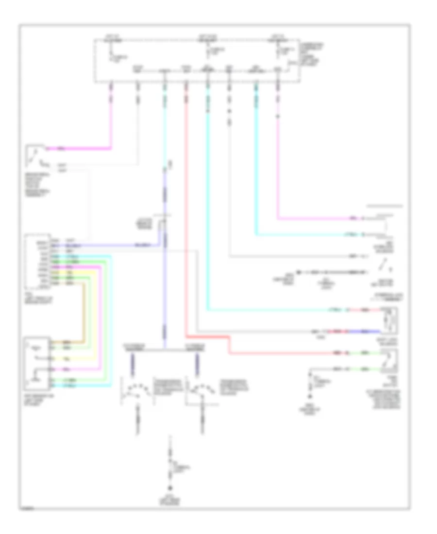
SHIFT INTERLOCK
Shift Interlock Wiring Diagram for Honda Insight EX 2014
List of elements for Shift Interlock Wiring Diagram for Honda Insight EX 2014:
- A/t gear position indicator panel light/park pin switch/shift lock solenoid
- A11
- A18
- A19
- A25
- A26
- A35
- A36
- A42
- Acc
- App sensor a/b (left side of dash)
- Apsa
- Apsb
- Atp-p
- Atpp
- B14
- B28
- B32
- B35
- Bksw
- Brake pedal position switch (top of brake pedal assembly)
- C103
- C302
- Fuse 14 7.5a
- Fuse 22 7.5a
- Fuse 24 10a
- G101 (left rear of engine)
- G502 (center of dash)
- Hot at all times
- Hot in acc or on
- Hot in on or start
- Ig 1 meter
- Ignition key switch
- J/c c104 (rear of engine)
- Key interlock solenoid
- Key lock sol
- Key sw
- M17
- M18
- M34
- Micu
- P-pin sw
- Park pin switch
- Pcm (left front of engine compt)
- Pnk
- Q10
- Red
- S11 (thermal joint)
- S2 (thermal joint)
- Sg4
- Sg5
- Shift lock solenoid
- Sls
- Steering lock assembly
- Stop sw
- Transmission range switch (on transaxle housing)
- Transmission range switch (on transaxle housing) l
- Under-dash fuse/relay box (under left side of dash)
- Vcc4
- Vcc5
- W/ paddle shifters
- W/o paddle shifters
 English