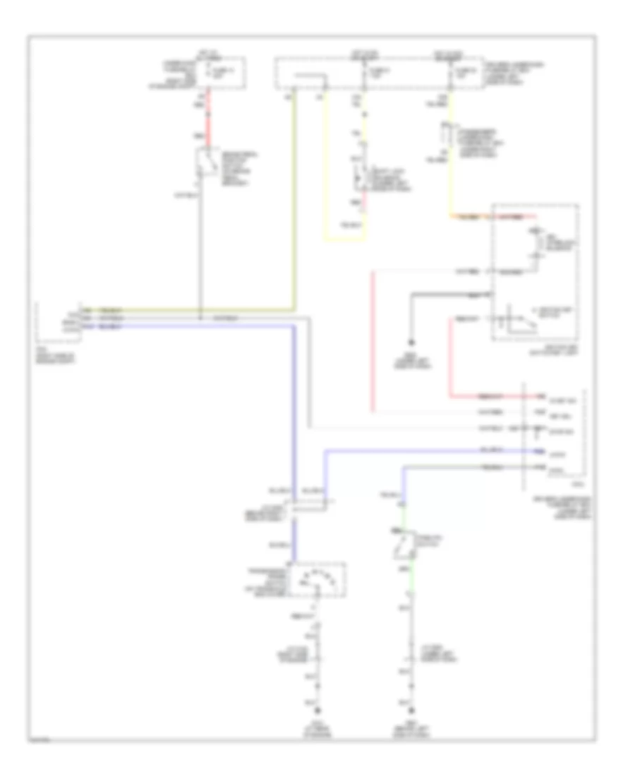
SHIFT INTERLOCK
Shift Interlock Wiring Diagram for Honda Odyssey EX 2005
List of elements for Shift Interlock Wiring Diagram for Honda Odyssey EX 2005:
- (under left side of dash)
- A12
- Atp-p
- Bksw
- Brake pedal position switch (on brake pedal bracket)
- Driver's under-dash fuse/relay box
- Driver's under-dash fuse/relay box (under left side of dash)
- Fuse 13 20a
- Fuse 21 7.5a
- Fuse 32 10a
- G101 (at rear of engine)
- G501 (behind left side of dash)
- G502
- Hot at all times
- Hot in acc or start
- Hot in on or start
- Ig key sw
- Ignition key switch
- Ignition key switch/key light
- J/c c102 (right side of engine)
- J/c c405 (behind right side of dash)
- J/c c502 (under left side of dash)
- Key interlock solenoid
- Key sol
- Micu
- N26
- N36
- P-pin
- P13
- P29
- P30
- Park pin switch
- Passenger's under-dash fuse/relay box (under right side of dash)
- Pcm (right side of engine compt)
- Red
- Shift lock solenoid (under left side of dash)
- Sls
- Stop sw
- Transmission range switch (on transaxle end cover)
- Under-hood fuse/relay box (right side of engine compt)
- X34
 Русский