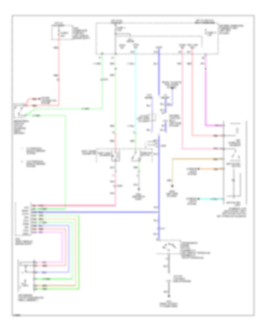
SHIFT INTERLOCK
Shift Interlock Wiring Diagram for Honda Odyssey Touring 2013
List of elements for Shift Interlock Wiring Diagram for Honda Odyssey Touring 2013:
- 20a
- A16
- A18
- A19
- A24
- A25
- A26
- A27
- App sensor (top of accelerator pedal assembly)
- Apsa
- Apsb
- Atp-p
- Bksw
- Brake pedal position switch (on brake pedal bracket)
- C101
- C205
- C212
- Driver's junction box 2 (left side of dash)
- Driver's under-dash fuse/relay box (left end of dash)
- Fuse 11 7.5a
- Fuse 13 7.5a
- Fuse 9
- G101 (front of right cylinder head)
- G402 (left side of dash)
- G403 (center of dash)
- Hot at all times
- Hot in on or start
- Hot w/ acc cut relay energized
- Ig 1 meter
- Ig key sw
- Ignition key light
- Ignition key switch
- Interior lights system
- J/c c102 (top right side of engine)
- J/c c407 (left side of dash)
- Key interlock solenoid
- Key lock sol-
- Main under-hood fuse box (left side of engine compt)
- Memory
- P-pin sw
- Park pin switch
- Pcm (right rear of engine compt)
- Pnk
- Power distribution system
- Q17
- Q18
- Q19
- Red
- Sg3
- Sg4
- Shift lever connector
- Shift lock solenoid
- Sls
- Steering lock (ignition key light/ ignition key switch/ key interlock solenoid)
- Stop sw
- Transmission range switch (5-speed a/t: left side of transaxle) (6-speed a/t: top of transaxle)
- Trunk, tailgate, fuel doors system
- Vcc3
- Vcc4
- W/ parking & backup sensor system
- W/o
- W/o parking & backup sensor system
 English