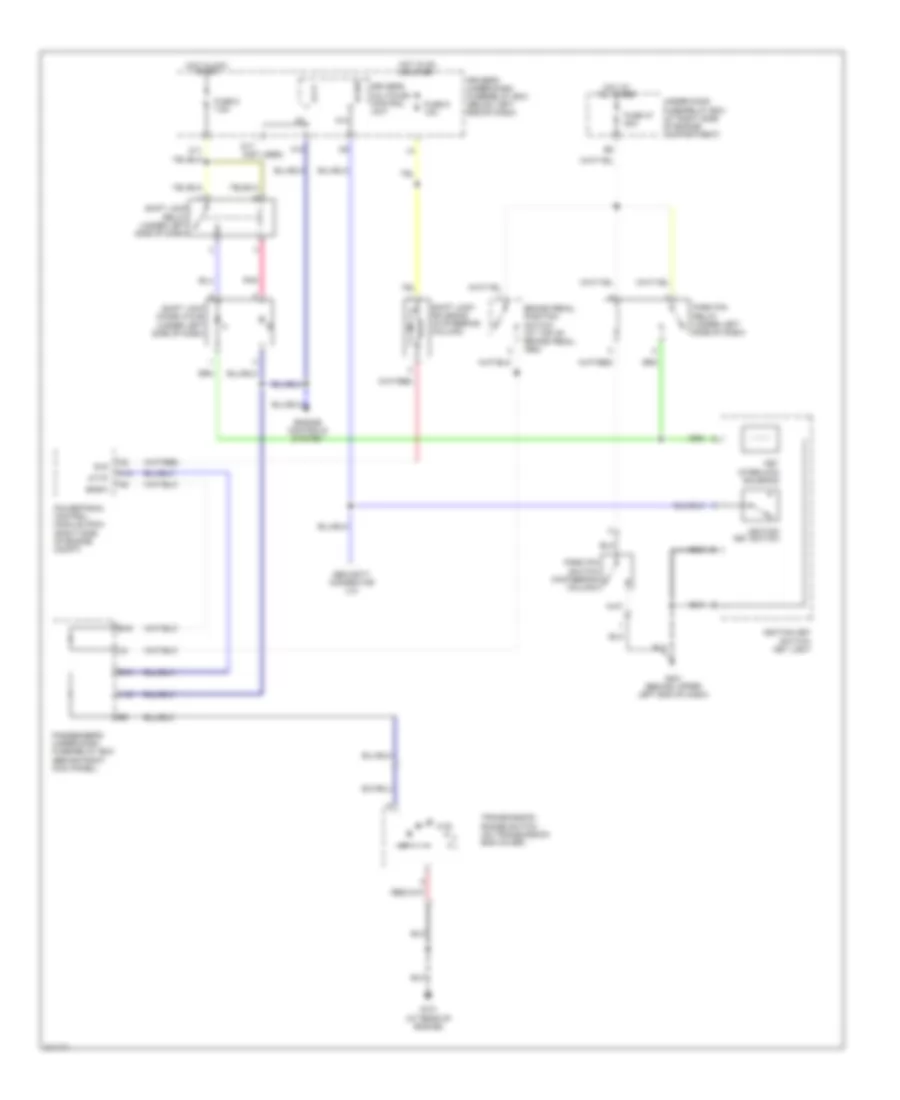
SHIFT INTERLOCK
Shift Interlock Wiring Diagram for Honda Pilot EX 2005
List of elements for Shift Interlock Wiring Diagram for Honda Pilot EX 2005:
- (not used)
- A12
- A13
- At-p
- Attp
- B10
- B16
- Bksw
- Brake pedal position switch (at top of brake pedal arm)
- D17
- Driver's multiplex control unit
- Driver's under-dash fuse/relay box (below left end of dash)
- Engine controls system
- Fuse 47 20a
- Fuse 8 7.5a
- Fuse 9 10a
- G101 (at rear of engine)
- G401 (behind upper left end of dash)
- H12
- Hot at all times
- Hot in acc or on
- Hot in on or start
- Ig sw
- Ignition key switch
- Ignition key switch/ key light
- K10
- Key interlock solenoid
- Park pin relay (under left side of dash)
- Park pin switch (in steering column)
- Passenger's under-dash fuse/relay box (behind right kick panel)
- Pnk
- Powertrain control module (pcm) (right side of engine compt)
- Security connector (lx)
- Shift lock diode (a & b) (under left side of dash)
- Shift lock relay (under left side of dash)
- Shift lock solenoid (in steering column)
- Sls
- Transmission range switch (on transmission end cover)
- Under-hood fuse/relay box (at right side of engine compartment)
 Русский