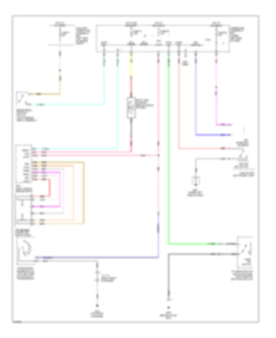
SHIFT INTERLOCK
Shift Interlock Wiring Diagram for Honda Pilot Touring 2009
List of elements for Shift Interlock Wiring Diagram for Honda Pilot Touring 2009:
- (not used)
- A/t gear position indicator panel light/park pin switch/d3 switch
- A16
- A18
- A19
- A24
- A25
- A26
- A27
- Acc
- App sensor (under left side of dash)
- Apsa
- Apsb
- Atp-p
- Atpp
- Auxiliary under-hood fuse/relay box (left side of engine compt)
- Bksw
- Brake pedal position switch (top of brake pedal assembly)
- F25
- F27
- F30
- Fuse 10 7.5a
- Fuse 11 20a
- Fuse 35 10a
- G101 (top front of engine)
- G401 (under left side of dash)
- G403 (behind glove box)
- Hot at all times
- Hot in acc or on
- Hot in on or start
- Ig 1 meter
- Ig key sw
- Ignition key switch
- Ignition key switch/key light
- J/c 112 (right front of engine)
- Key interlock solenoid
- Key lock sol
- Micu
- P-pin sw
- Park pin switch
- Pcm (right side of engine compt)
- Pnk
- R16
- Red
- Sg3
- Sg4
- Shift lock solenoid (behind middle of dash)
- Sls
- Stop sw
- Transmission range switch (top left side of automatic transmission)
- Under-dash fuse/relay box (under left side of dash)
- Vcc3
- Vcc4
 English