SHIFT INTERLOCK
Ignition Lock Solenoid Wiring Diagram for Hummer H2 2007

List of elements for Ignition Lock Solenoid Wiring Diagram for Hummer H2 2007:
- (not used)
- (on left front of engine compt)
- (on left side of dash, near left kick panel) g200
- Automatic transmission
- Automatic transmission shift lever (closed in park)
- C175
- E11
- F10
- Hot in acc/ run/start
- I/p fuse block (on lower left side of dash)
- Ign 0 fuse 10a
- Ignition lock cylinder control actuator (behind ignition switch assembly)
- Ignition lock cylinder control switch
- Pnk
- Powertrain control module (pcm)
- S218
- Underhood fuse block (at left side of engine compt, near battery)
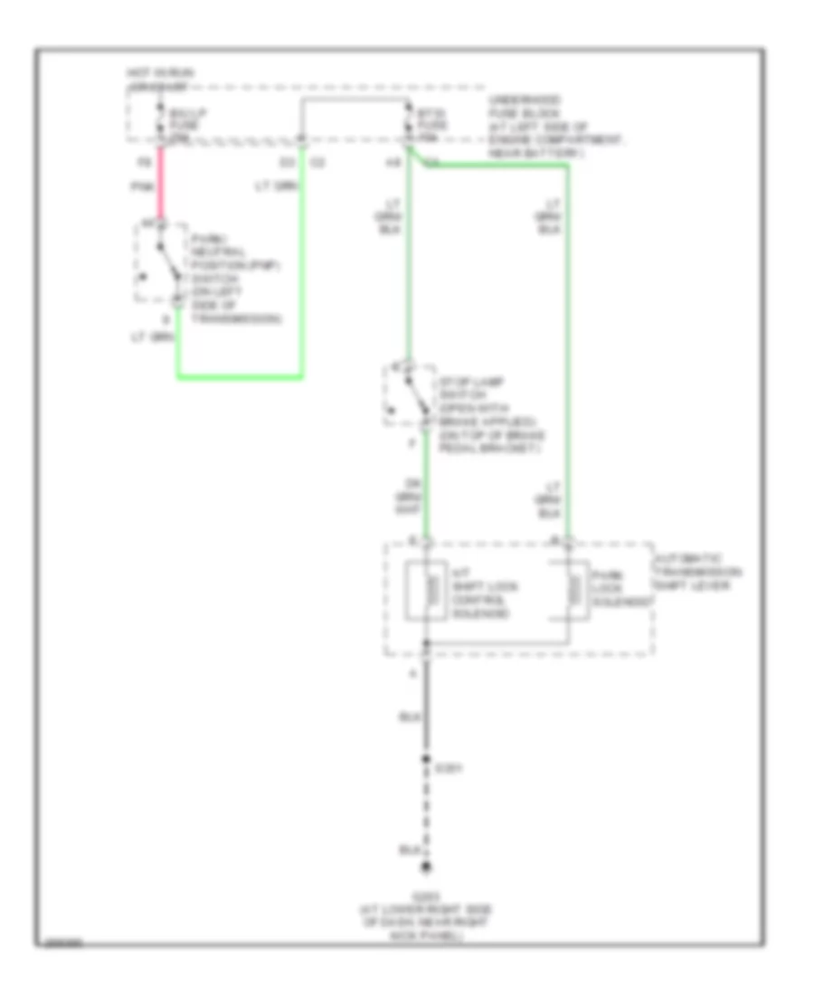
Shift Interlock Wiring Diagram for Hummer H2 2007
List of elements for Shift Interlock Wiring Diagram for Hummer H2 2007:
- A/t shift lock control solenoid
- Automatic transmission shift lever
- B/u lp fuse 20a
- Btsi fuse 10a
- G203 (at lower right side of dash, near right kick panel)
- Hot in run or start
- Park lock solenoid
- Park/ neutral position (pnp) switch (on left side of transmission)
- Pnk
- S351
- Underhood fuse block (at left side of engine compartment, near battery)