SHIFT INTERLOCK
Ignition Lock Solenoid Wiring Diagram for Hummer H3 2007

List of elements for Ignition Lock Solenoid Wiring Diagram for Hummer H3 2007:
- Automatic transmission floor shift control (beneath center console)
- Body control module (bcm) (behind right front kick panel)
- G106 (on right inner front wheel well)
- Hot at all times
- Ignition lock cylinder control actuator (on upper right side of steering column)
- Park position switch (closed in park)
- Rap relay
- Rap/accy relay
- S143
- S205
- Underhood fuse block (above left front wheel well)
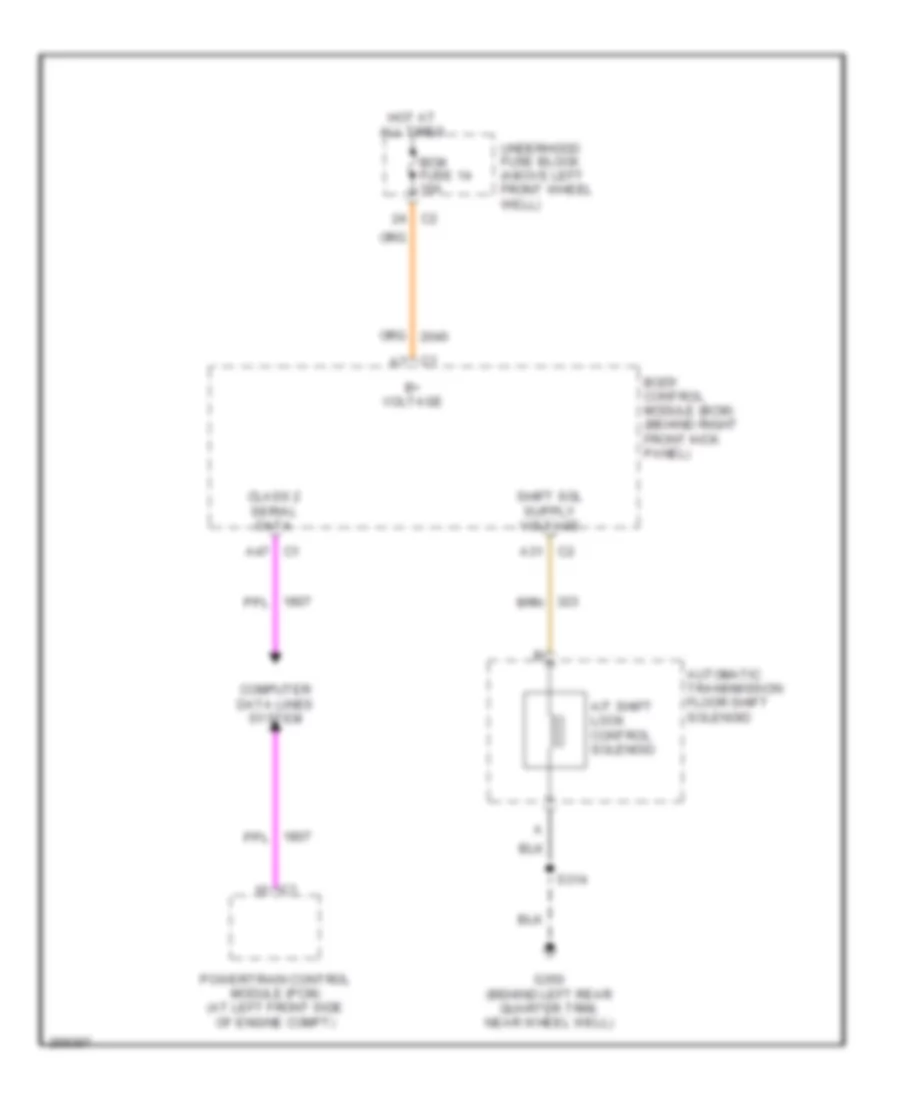
Shift Interlock Wiring Diagram for Hummer H3 2007
List of elements for Shift Interlock Wiring Diagram for Hummer H3 2007:
- A/t shift lock control solenoid
- A31 c2
- A47 c1
- Automatic transmission floor shift solenoid
- B+ voltage
- Bcm fuse 14 10a
- Body control module (bcm) (behind right front kick panel)
- C1 a7
- Class 2 serial data
- Computer data lines system
- G350 (behind left rear quarter trim, near wheel well)
- Hot at all times
- Powertrain control module (pcm) (at left front side of engine compt)
- S314
- Underhood fuse block (above left front wheel well)