SHIFT INTERLOCK
Ignition Lock Solenoid Wiring Diagram for Hummer H3 2010

List of elements for Ignition Lock Solenoid Wiring Diagram for Hummer H3 2010:
- Automatic transmission shift lever
- Body control module (bcm) (behind right front kick panel)
- C12
- G106 (on right inner front wheelwell)
- Hot at all times
- Ignition lock cylinder control actuator (on upper right side of steering column)
- J143
- J205
- Park position switch (closed in park)
- Rap relay
- Rap/accy relay 88
- S/roof frt/wpr fuse 9 15a
- Underhood fuse block (above left front wheelwell)
- X200
- X201
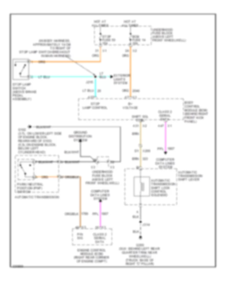
Shift Interlock Wiring Diagram for Hummer H3 2010
List of elements for Shift Interlock Wiring Diagram for Hummer H3 2010:
- (in body harness, approximately 14 cm to right of stop lamp switch breakout in main harness)
- A31 x2
- A37
- A47 x1
- Automatic transmission
- Automatic transmission shift lever
- Automatic transmission shift lock control solenoid
- B+ voltage
- Bcm fuse 14 10a
- Body control module (bcm) (behind right front kick panel)
- Class 2 serial data
- Computer data lines system
- D1 x200
- Engine control module (ecm) (right rear corner of engine compt)
- Exterior lights system
- G102 (3.7l: on lower left side of engine block, rearward of g103) (5.3l:on engine block, below left cylinder head)
- G350 (suv: behind left rear quarter trim, near wheelwell) (truck: base of right "c" pillar)
- Ground distribution system
- Hot at all times
- J215
- J314
- P/n sig
- Park/ neutral position (pnp) switch
- Shift sol ctrl
- Stop fuse 50 15a
- Stop lamp control
- Stop lamp switch (above brake pedal assembly)
- Underhood fuse block (above left front wheelwell)
- X1 a7