
SHIFT INTERLOCK
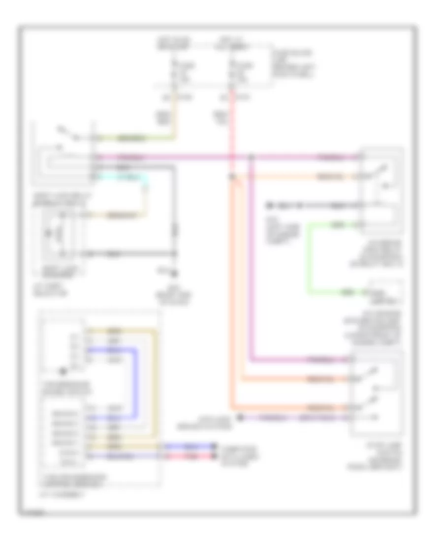
Shift Interlock Wiring Diagram for Infiniti M35 x 2010
List of elements for Shift Interlock Wiring Diagram for Infiniti M35 x 2010:
ANTI-LOCK BRAKESCOOLING FANANTI-THEFTBODY CONTROL MODULESDEFOGGERSAIR CONDITIONINGCOMPUTER DATA LINESCRUISE CONTROLGROUND DISTRIBUTIONELECTRONIC POWER STEERINGENGINE PERFORMANCEHEADLIGHTSINTERIOR LIGHTSEXTERIOR LIGHTSMEMORY SYSTEMSHORNNAVIGATIONINSTRUMENT CLUSTERPOWER DISTRIBUTIONPASSIVE RESTRAINTSPOWER DOOR LOCKSPOWER MIRRORSPOWER WINDOWSPOWER TOP/SUNROOFSHIFT INTERLOCKPOWER SEATSSTARTING/CHARGINGTRANSMISSIONSUPPLEMENTAL RESTRAINTSRADIOWARNING SYSTEMSTRUNK, TAILGATE, FUEL DOORWIPER/WASHER