
SHIFT INTERLOCK
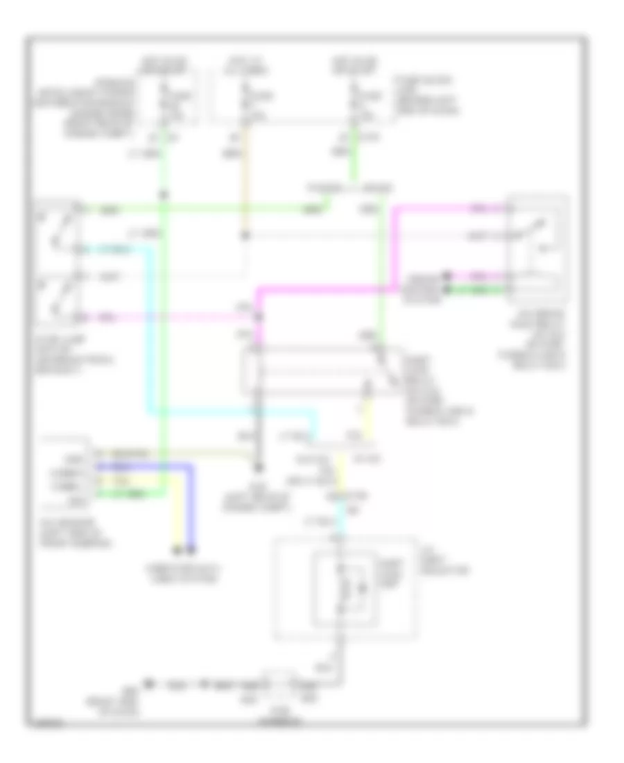
Shift Interlock Wiring Diagram for Infiniti M56 x 2013
List of elements for Shift Interlock Wiring Diagram for Infiniti M56 x 2013:
AIR CONDITIONINGCOOLING FANANTI-THEFTANTI-LOCK BRAKESCRUISE CONTROLBODY CONTROL MODULESDEFOGGERSCOMPUTER DATA LINESENGINE PERFORMANCEELECTRONIC POWER STEERINGHEADLIGHTSGROUND DISTRIBUTIONEXTERIOR LIGHTSHORNINSTRUMENT CLUSTERNAVIGATIONINTERIOR LIGHTSMEMORY SYSTEMSPASSIVE RESTRAINTSPOWER SEATSPOWER DISTRIBUTIONPOWER TOP/SUNROOFPOWER DOOR LOCKSPOWER MIRRORSTRANSMISSIONSHIFT INTERLOCKSTARTING/CHARGINGRADIOPOWER WINDOWSTRUNK, TAILGATE, FUEL DOORWARNING SYSTEMSSUPPLEMENTAL RESTRAINTSWIPER/WASHER