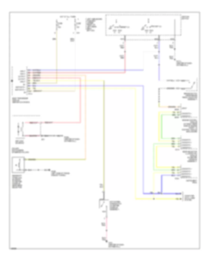
SHIFT INTERLOCK
Shift Interlock Wiring Diagram for Jaguar XJR 2003
List of elements for Shift Interlock Wiring Diagram for Jaguar XJR 2003:
- (0) off
- Acc (i)
- B+
- Body processor module (behind glove box)
- Brake switch (near brake pedal mounting assembly)
- Ca1
- Can data +
- Can data -
- Cc14
- Cc2r (left side of trans- mission tunnel)
- Cc3l (center of dash, on firewall)
- Column switchgear (steering column)
- Computer data lines system
- Em82
- Em83
- Engine control module (at right rear side of engine compt, in control module enclosure)
- Fc14
- Fc17l (center of dash, on firewall)
- Fc24
- Fc29l (center of dash, on firewall)
- Fuse 15a
- Gear selector illumination module (in center console assembly)
- Gearshift interlock solenoid (in center console, near gear selector)
- Hot at all times
- Ignition switch
- Input
- Instrument pack
- Keylock solenoid
- Left heelboard fuse box (under front of left rear seat bottom)
- Nca
- Not-in-park microswitch (in center console assembly)
- Output
- Run (ii)
- Sc1
- Scp data +
- Scp data -
- Start (iii)
 English