SHIFT INTERLOCK
Park Brake Release Wiring Diagram for Land Rover Discovery 2 2014

List of elements for Park Brake Release Wiring Diagram for Land Rover Discovery 2 2014:
- C33g
- C33h
- C3bp01f
- C44d
- C44e
- C44f
- C4br02g
- Central junction box (cjb) (behind glove compt)
- Computer data lines system
- Electric park brake control module (left rear corner of luggage compt)
- Electric park brake lamp (amber)
- Electric park brake lamp (red)
- Electric park brake switch
- Fuse 30a
- Fuse 5a
- G3d127 (under rear of front passenger's seat)
- G4d152 (on left side of luggage compt)
- Gnd motor l
- Gnd motor r
- Hot at all times
- Hot w/ ignition relay energized
- Hs can h
- Hs can l
- Ign
- Ill
- Instrument cluster
- Interior lights system
- Left electric park brake actuator (on left rear brake assembly)
- Lh motor +ve
- Lh motor -ve
- Rear junction box (rjb) (left front corner of luggage compt)
- Red
- Rh motor +ve
- Rh motor -ve
- Right electric park brake actuator (on right rear brake assembly)
- Sw gnd
- Sw1
- Sw2
- Sw3
- Sw4
- Vbatt motor lh
- Vbatt motor rh
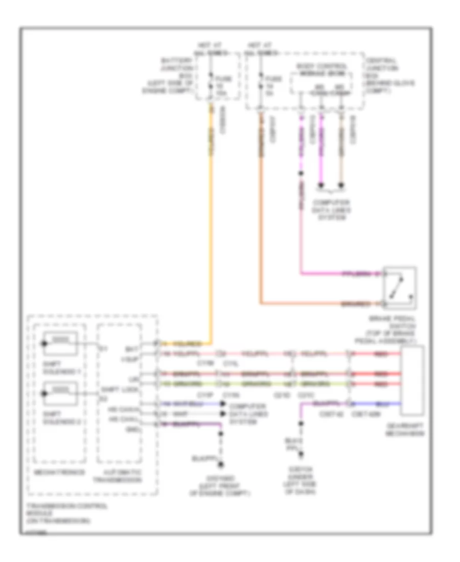
Shift Interlock Wiring Diagram for Land Rover Discovery 2 2014
List of elements for Shift Interlock Wiring Diagram for Land Rover Discovery 2 2014:
- Automatic transmission
- Bat
- Battery junction box (left side of engine compt)
- Body control module (bcm)
- Brake pedal switch (top of brake pedal assembly)
- C11l
- C11m
- C11n
- C11p
- C1bb03a
- C21d c21c
- C2bp01b
- C3bp01f
- C3bp01g
- C3et42m c3et42
- Central junction box (behind glove compt)
- Computer data lines system
- Fuse 15a
- Fuse 5a
- G1d108d (left front of engine compt)
- G3d134 (under left side of dash)
- Gearshift mechanism
- Gnd
- Hot at all times
- Hs can h
- Hs can l
- Lin
- Mechatronics
- Ms canh
- Ms canl
- Red
- Shift lock
- Shift solenoid 1
- Shift solenoid 2
- Transmission control module (on transmission)
- Vsup
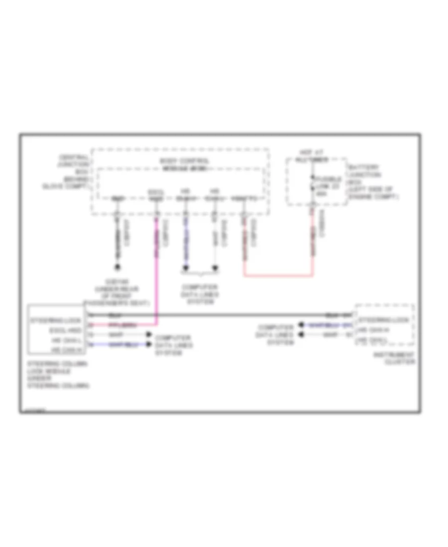
Steering Column Wiring Diagram for Land Rover Discovery 2 2014
List of elements for Steering Column Wiring Diagram for Land Rover Discovery 2 2014:
- Battery junction box (left side of engine compt)
- Body control module (bcm)
- C1bb01a
- C1bp01d
- C1bp01e
- C2bp01c
- C3bp01f
- Central junction box (behind glove compt)
- Computer data lines system
- Escl hsd
- Fusible link 23 40a
- G3d140 (under rear of front passenger's seat)
- Gnd
- Hot at all times
- Hs can h
- Hs can l
- Instrument cluster
- Steering column lock module (under steering column)
- Steering lock
- Vbatt3