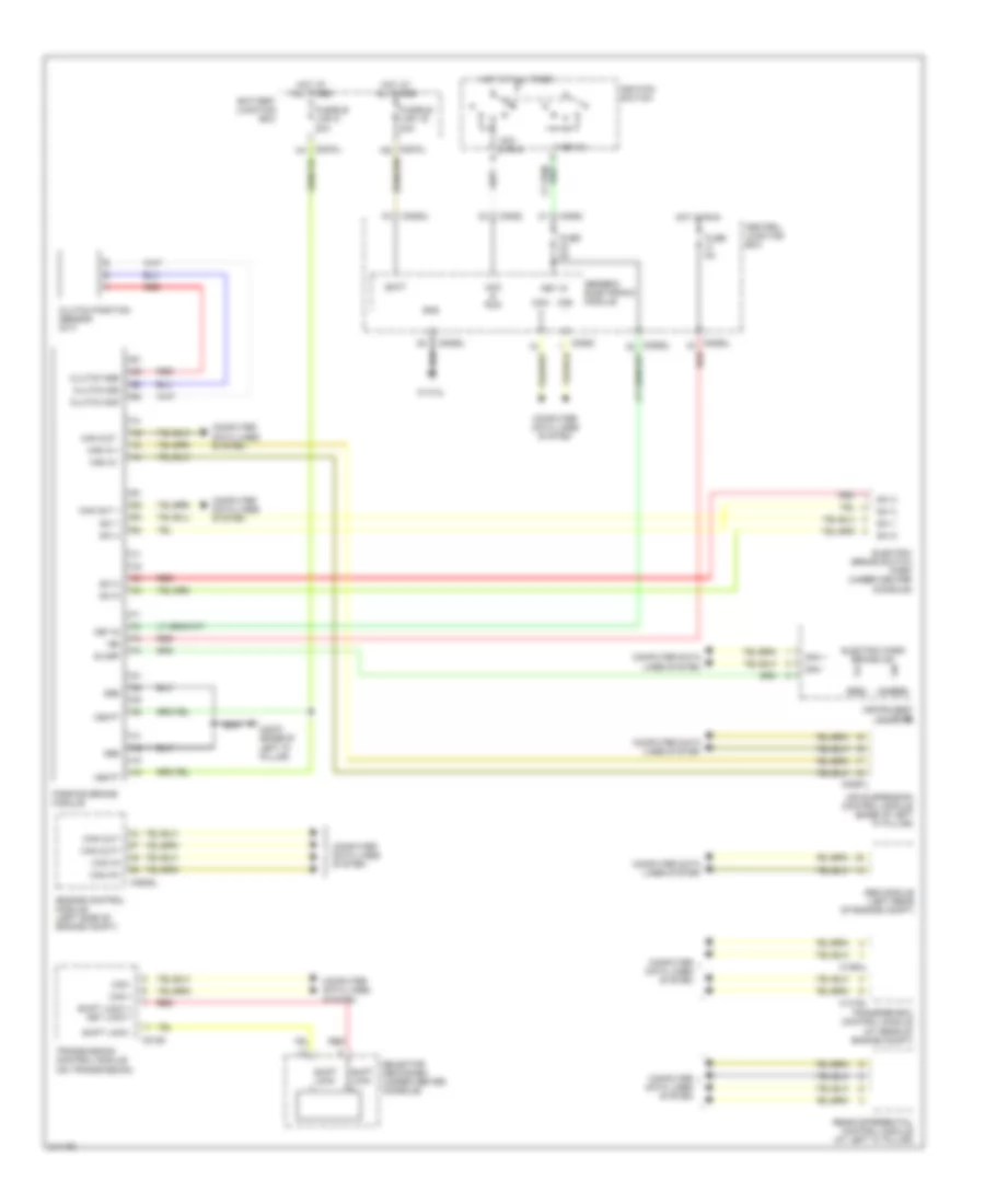
SHIFT INTERLOCK
Shift Interlock Wiring Diagram for Land Rover Discovery 3 SE 2006
List of elements for Shift Interlock Wiring Diagram for Land Rover Discovery 3 SE 2006:
- (amber)
- (red)
- Abs module (left rear of engine compt)
- Acc & run
- Air suspension control module (base of left "a" pillar)
- Batt
- Battery junction box
- C0193
- C0570l
- C0580
- C0582
- C0583l
- C0585l
- C0586l
- C0635l
- C0867l
- C1319l
- C1413l
- C1854l
- C2570 (base of left "d" pillar)
- Can +
- Can -
- Can in +
- Can in -
- Can in+
- Can in-
- Can out +
- Can out -
- Can out+
- Can out-
- Central junction box
- Clutch gnd
- Clutch position sensor (m/t)
- Clutch sig
- Clutch sup
- Computer data lines system
- Electric brake switch park (under center console)
- Electric park brake ind
- Engine control module (left side of engine compt)
- Fuse 5a
- Fusible link 16 40a
- Fusible link 8 30a
- Generic electronic module
- Gnd
- Hot at all times
- Hot in run
- Ign
- Ignition switch
- Instrument cluster
- Key in
- Key-in
- Parking brake module
- Rear differential control module (at left "c" pillar)
- Red
- Selector mechanism (under center console)
- Shift lock +
- Shift lock +/ key lock +
- Shift lock -
- Slamp
- Sw 1
- Sw 2
- Sw 4
- Sw 5
- Transfer box control module (at rear of engine compt)
- Transmission control module (on transmission)
- Vbatt
 English