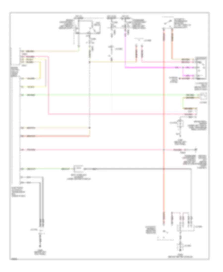
SHIFT INTERLOCK
Shift Interlock Wiring Diagram for Land Rover Freelander SE 2004
List of elements for Shift Interlock Wiring Diagram for Land Rover Freelander SE 2004:
- (behind center console)
- 87a
- Automatic gearbox selector indicator
- Automatic transmission selector (at left front of engine compt)
- Brake pedal sensor (under left side of dash, near brake pedal support)
- C0331
- C0550
- C0562 (behind left kick panel)
- C0575
- C0581
- C0582
- C0589
- C0604
- C1967 (behind left kick panel)
- Central control unit (behind passenger compt fuse box)
- Electronic automatic transmission ecu (inside "e" box)
- Engine compartment fuse box (left rear of engine compt)
- Engine control module (inside e-box)
- Fuse 10a
- Fuse 15a
- Hot at all times
- Hot in on or start
- Illumination relay (behind right side of dash)
- Interior lights system
- J/c 0285
- J/c 0292
- J/c 0294
- J/c 0550
- J/c 0723
- Main relay
- Passenger compartment fuse box (behind left side of dash)
- Shift interlock solenoid (under center console)
 English