SHIFT INTERLOCK
Park Brake Release Wiring Diagram for Land Rover Range Rover 2013

List of elements for Park Brake Release Wiring Diagram for Land Rover Range Rover 2013:
- C2bp01f
- C2mc01a
- C32-x1
- C32-x1 c32-x2
- C32-x2
- C44-a1
- C44-a2
- C44-e1
- C44-e2
- C4br02a
- Central junction box (cjb) (behind left side of dash)
- Computer data lines system
- Electric park brake switch
- Electric parking brake module (right side of cargo area)
- Fuse 30a
- Fuse 5a
- G3d375 (left side of rear seat entertainment console)
- G4d351 (right rear of cargo area)
- Gnd motor l
- Gnd motor r
- Hot at all times
- Hot w/ ignition relay energized
- Hs can h
- Hs can l
- Ign
- Ill
- Instrument cluster
- Interior lights system
- Left electric park brake actuator
- Lh motor +ve
- Lh motor -ve
- Rear junction box (rjb) (right side of cargo area)
- Rh motor +ve
- Rh motor -ve
- Right electric park brake actuator
- Sw gnd
- Sw1
- Sw2
- Sw3
- Sw4
- Temp lh
- Temp rh
- Terrain response switch pack
- Vah led
- Vah sw
- Vbatt motor lh
- Vbatt motor rh
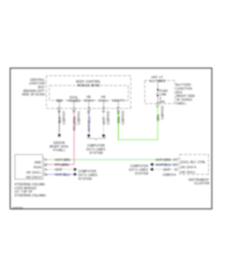
Steering Column Wiring Diagram for Land Rover Range Rover 2013
List of elements for Steering Column Wiring Diagram for Land Rover Range Rover 2013:
- Battery junction box (right side of cargo area)
- Body control module (bcm)
- C2bp01c
- C2bp01d
- C2bp01e
- C2bp01f
- C2mc01a
- C4bf01d
- Central junction box (behind left side of dash)
- Computer data lines system
- Escl power
- Escl rly ctrl
- Fuse link 60a
- G2d238 (right kick panel)
- Gnd
- Hot at all times
- Hs can h
- Hs can l
- Instrument cluster
- Pwr
- Steering column lock module (at top of steering column)
- Vbatt1