
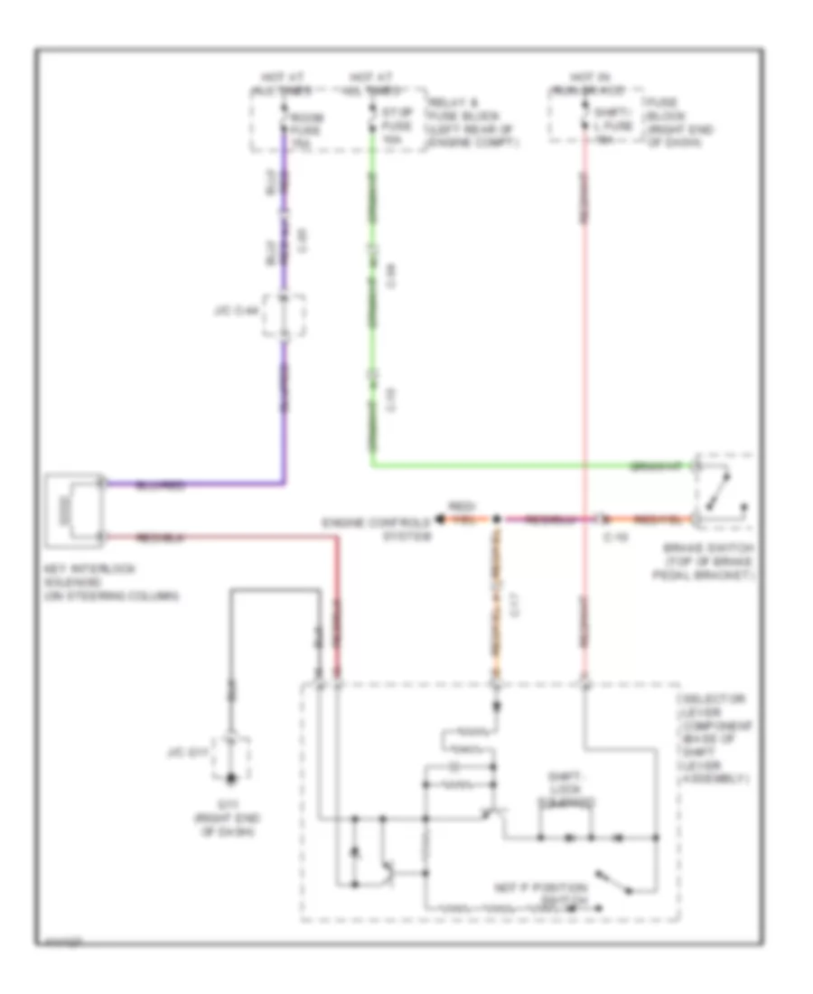
SHIFT INTERLOCK
Shift Interlock Wiring Diagram for Mazda 5 Grand Touring 2013
List of elements for Shift Interlock Wiring Diagram for Mazda 5 Grand Touring 2013:
AIR CONDITIONINGANTI-LOCK BRAKESBODY CONTROL MODULESCOOLING FANANTI-THEFTCOMPUTER DATA LINESENGINE PERFORMANCEDEFOGGERSELECTRONIC POWER STEERINGCRUISE CONTROLEXTERIOR LIGHTSGROUND DISTRIBUTIONHEADLIGHTSINTERIOR LIGHTSHORNINSTRUMENT CLUSTERPOWER DISTRIBUTIONNAVIGATIONPOWER SEATSPOWER MIRRORSPOWER WINDOWSPOWER DOOR LOCKSPOWER TOP/SUNROOFTRANSMISSIONRADIOTRUNK, TAILGATE, FUEL DOORSUPPLEMENTAL RESTRAINTSSTARTING/CHARGINGWARNING SYSTEMSSHIFT INTERLOCKWIPER/WASHER